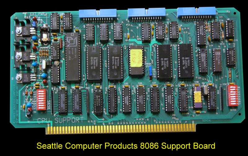
The board had room for an optional onboard ROM monitor. This was usually
some form of the SCP supplied
8086 monitor. The ROM could be either an Intel-type 2716 or 2732. It
resided near the end or memory, as determined by either the usual 16 address
lines, or by IEEE 696, 20 address lines (extended addressing).
The board could drive the PHANTOM line to allow a
memory board to overlap with it on the bus. This could be disabled with an
software output command.
A serial communication port, including RS-232 drivers with full
handshaking was included. A software controlled baud rate generator
allows almost any conceivable data rate to be used.
There was a parallel input port, latched and with full handshaking.
This port could provide +5V or +8V to power an external device (such as a
keyboard). There also was a parallel output port. Again full
handshaking was provided with an output that may be statically latched and
driving at all times or configured for 3-state output which allowed
bidirectional operation.
There was an onboard vectored interrupt controller. This provided 15
levels of vectored interrupts, expandable to 64 through 'slave' controllers
on other cards (such as the SCP
Multiport Serial card).
The board had two general-purpose timer/counters. Each was 16 bits wide. One
could be combined with the time-of-day clock to count days.
There was also on board a time-of-of day clock. Time of day was kept in
24-hour format to 0.01 second. Power to run the clock may be provided from
an external source, such as a battery, to keep the clock running when the
computer power was off. If time of day was not needed, the clock could be
used as two general-purpose 16-bit timers.
Finally like the
TDL SMB board
there was an "IOBYTE" type "sense switch" input port. This allowed the
reading the setting of an 8-position DIP switch for the purpose of setting
software options or configuration information.
Each of the above functions were controlled by a block of 16 I/O ports. The
upper 4 bits of the 8-bit I/O address are compared with a switch setting to
enable the board as a whole; the lower 4 bits select the particular function
on the board.


