S100 Computers

Home S-100 Boards History New Boards Software Boards For Sale
Forum Other Web Sites News Index    
 
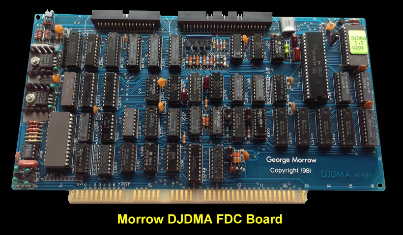
Morrow - Disk Jockey DMA Floppy Disk Controller
This was one of Morrows last S-100 boards. It first came out in 1982. Like the earlier Disk Jockey 2D, it could control up to four 5" and 8" floppy disk drives

DJDMA-FDC

The Disk Jockey/Direct Memory Access (DJDMA) Floppy Disk Controller was a single board for the S-100 bus. It communicated with both 8 inch and 5 inch floppy disk drives. Up to eight drives could be connected to the controller - with the limitation that no more than four of each type could be accommodated. Special programmable bipolar LSI logic made it possible to read and write media in almost any format, be it hard or soft sectored disks. Normally the controller was used for soft-sectored IBM compatible 8 inch media. However many used it for  hard-sectored North Star compatible 5 inch media.
 
The controller had its own Z-80 4MHz microprocessor which was used to supervise data transfers between the disk drive and the system memory without intervention of the main CPU. This relieves the main CPU of time consuming processes which include head positioning, rotational delays, and the usual byte-by-byte transfer of data from the diskette to main memory. As a result, transfers are faster and more efficient. Moreover, the main CPU has more time for data processing, and thus, supports more users and/or tasks. The main advantage of the DJDMA controller over almost all the others was its "glitch free"  DMA channel. This advanced channel concept allowed the controller to communicate with S-100 memory by "stealing" bus cycles from the main CPU. This idea of an intelligent I/O channel was first implemented by IBM on their famous 370 mainframes. For the first time, this powerful  concept had been implemented on  the S-100 bus.
 
The DMA channel had the full 24-bits of memory addressing as described in the proposed IEEE standard for the S-100 bus. Also, a great deal of care was been taken in the design of the interface circuitry so it conformed in every detail to this then new standard and still allowed the controller to work well with existing systems designed  before   the   standardization  effort  was   started. The controller is a temporary bus master, meaning that it had the same access to memory as the CPU whenever it has control. It also features priority logic which allows it to contend with up to sixteen other "temporary" masters that may also want to "steal" bus cycles from the main CPU,  or the  "permanent"   master. The controller acts as a temporary master (TMA). A temporary master may take control of the bus to perform a DMA operation. This is possible because both the TMA and the CPU drive control lines. The CPU, as permanent master, monitors signals from the TMA. When the TMA wants control, it first asserts a HOLD/ signal to  the CPU.     Assuming  the TMA has priority,  the CPU acknowledges this signal upon completion of the present bus cycle by returning a processor hold acknowledge (pHLDA) signal. Upon receipt of this signal, the TMA enables its control line and asserts a control disable (CDSB) signal, disabling the CPU's control line. The TMA then disables the CPU's data-out, address and status lines using DODSB/, ADSB/ and SDSB/ signals. At that point the TMA has complete control to perform its DMA operation. To return control to the CPU, the TMA first disables its own data-out, address and status lines, then re-enables the CPU's control lines, and simultaneously, its data-out, address and status lines. The TMA then releases its control line and makes false the HOLD/ signal, thus  returning f u11 control to the CPU. So far, the process has been described as if only one temporary master wanted control of the bus.
  
There can be up to 16 temporary masters on the bus. When there is more than one temporary master, they use the four DMA lines to decide who gets to assert HOLD. Any device requesting the bus places its TMA priority level on the bus, and circuitry on the device decides if it has the highest priority. The device with the highest priority (0F hex is highest) asserts HOLD/. It removes its priority from the DMA lines when it receives pHLDA from the permanent master. The features associated with the intelligent channel on the controller make it exceptionally desirable in multi-tasking and multi-user applications. In fact, many were tailored to enhance the performance of Morrow Designs new, powerful DECISION I multi­processing IEEE 696/S-100 machine. The DJDMA is an integral part of this advanced microcomputer system which incorporates many of the concepts originally introduced by IBM in their famous 370 series mainframes. The DJDMA can boot itself up on the bus and even has a primitive serial port which is intended for diagnostic purposes or possibly even integrating the controller into a larger S-100 system that has I/O that the boot disk is not aware of. Under no circumstances can it be used as a general purpose serial port to the system, however, since it is inactive during disk activity.
  
The manual for this board can be obtained here
.


Morrow S-100 Boards

24K RAM   64K RAM    Disk Jockey FDC     Multi I/O    SuperRAM     SwitchBoard    Z80 Board    Hard Disk Controller
DJ-DMA FDC  8K DRAM    HDC-DMA Controller

This page was last modified on 05/04/2016