A UART I/O Port FPGA Code Example. This
circuit example adds a very basic RS232 Serial Port to the
Shield Sockets of the V2 FPGA Prototype board. It assumes the
user is familiar with RS232 communication hardware. If not, please read the
discussion about our Serial IO board
here first.
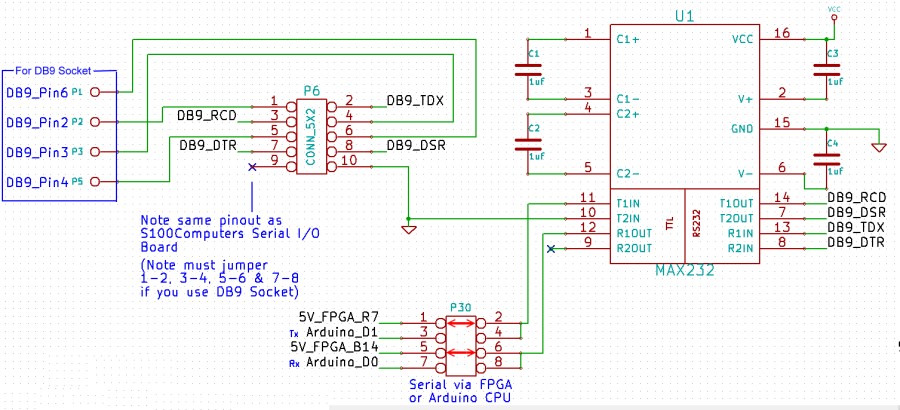
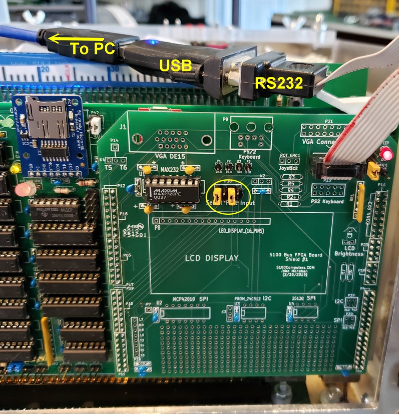
The actual hardware on the board consist of nothing more than a 2X5 pin connector
(to connect a ribbon cable to a DB9 socket at the back of your S100 box) and a
MAX232 RS232 voltage level shifter with 4 capacitors. Here is a schematic
and picture.
Be sure and jumper P30 1-2 and 5-6. The RS232 P6 pinout is the same as for
our Serial IO
board. So you can use that cable if you like.
The
Below is the core FPGA Code. The core UART Verilog file (Documented
Verilog UART by osdvu) was downloaded from
the OpenCores site
(Communications Controller section). The first thing to note is that the actual file is a Verilog file,
named in this example UART.v. Since we
are working with a
.bdf file we must
convert this file into a block diagram. You do this from the Quartus File
menu. Select "Create/Update"
and the "Create Symbol File From Current File".
Be sure and store it in the same folder as your main
.bdf file.
The UART diagram will appear as a rectangle with inputs on the LHS and outputs
on the RHS. Read the Verilog
UART.v file to understand their function in
the documentation.
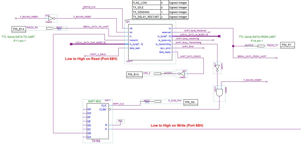
In my hands I found the UART code to flag when a character was received by the
"UART" was not latched. I needed a way to always know when a serial character
has been received. I modified the
UART.v
code to add an extra output as a flag (UART_DATA_READY)
when a character is received. This flag is reset when the data is read by
the S100 bus system by
PORT_A_READ.
Also because the gates in the FPGA is so fast, there needed to be a delay
in sending out the 8 data bits serially when pulsing "transmit"
high. A 74164 shift register did the trick using the S100
PHI signal as a clock.
Here is the core diagram.
The "UART" can be programmed to work at any common Baud
rate (see the
UART.V file in the
UART.zip file below). The two you may want to use are 9600 and 38400 Baud. 9600 is
the baud rate we used with the UART on out
PDP11 CPU board. You
can first use that board if you have it working to check your serial connection
to your PC is correct. Then switch the connection to this board. However
the most useful Baud rate is 38400 Baud. This is because it is the baud
rate our Z80 Master monitor uses to communicate over a serial line for the "X"
command. This command utilizes our
Serial IO board
to download .com (binary) files directly to a RAM location from (for example) your PC.
While the PDP11 board UART uses 2 stop bits, this UART works with 1 or 2 without
any modifications.
There are three very simple .Z80 files below that you can use to test your
circuit:-
IO_TEST1.Z80
This Z80 program (at 100H in RAM)
sends keyboard characters from our FPGA UART out via the RS232 Serial line to a
remote terminal.
IO_TEST2.Z80
This Z80 program (at 100H in RAM) reads keyboard characters from a remote
terminal via our FPGA UART and prints them on the S100 Bus console.
IO_TEST3.Z80
This Z80 program (at 100H in RAM) combines the above two programs. The typed
character on the remote terminal is returned an printed on the screen.
Please see
here to refresh your memory as to how to assemble, upload and run the above
programs utilizing this circuit. An example would be:-
Launch the ALTAIR.COM window DO CPM3
I:
SUBMIT IO_TEST3.SUB to generate a
IO_TEST3.COM file From Absolute Telnet (for example), launch a program to transmit over a
serial line in a XMODEM format IO_TEST3.COM
to your S100 system
Serial IO board.
On your S100 System Z80 Monitor use:-
X100
G100 This loads the program into the S100 bus RAM at 100H and the Z80 jumps to
that location.
As I said above the default MASTER monitor assumes 38400 baud., 1 stop
bit, no parity, so you can switch serial port connections quickly and easily.
You can usually use one serial connection. First upload the FPGA code.
Download the IO_TESTx.COM program from your PC
first (using XModem or an equivalent). Then switch the serial connection to this
board. Then jump to 100H in RAM to launch the program(s).
Please take time to fully understand the above FPGA code
and what is going on. This apparently very simple "program" encapsulates
many of the major concepts of FPGA programming. Try and understand the
function of everything there.
BTW this RS232 UART/Port is an absolute bare bones connection. I use an
RS232->USB adaptor to interface with my PC. A classical RS232 Port
should also implement RST, CTS, DTR etc. signals.