A Basic FPGA VGA Text Display Code Example.
Here we will use
our V2 FPGA Prototype board to send text
to a
VGA video display. Surprisingly I found finding a good simple working
example on the Web difficult. There are numerous examples of using FPGAs
to display colors, pictures etc. What I wanted was a simple "TTY
Terminal" display the could be incorporated into other FPGA projects. Long
story short, the best example I found was the excellent example by Javier
Valcarce, see
here. There were a few problems however. Javier wrote his code
for Xilinx/Spartan FPGA's. Unlike Quartus data for FPGA ROM's (in our case
the character lookup table code) is expected to be in a ".coe"
format. I had to get creative and use the Microsoft Visual C editor
and a Z80 Assembler to convert his
lat0-12.txt
file into a lat0-12.HEX
file readable by Quartus.
I have put together (see below), two simple/crude Z80 demo code examples to
run with your z80 and this S100 bus V2 FPGA prototype board. The first called
FPGA_VGA.Z80 is very simple. This is not a bullet-proof extensive terminal emulator. Look
upon it as a simple Teletype terminal. Carriage returns are translated into
CR+LF's. FF's clear the screen. Tabs and other cursor positioning is not
implemented. While the code is capable of 80X40 lines, I find on my (old) VGA
terminals it's best to stick to, at the most, 80X36 lines.
I have also written a more extensive VGA Character terminal called
VGA_TTY.Z80. This one is more extensive and
includes cursor positioning for FF, CR, LF, TAB, BS, DEL etc. It can for example
be used directly with our Z80 Monitor. Both can be downloaded from the
bottom of this page.
In my hands at least, there is a "quark" in Javier's "vga80X40.vhd"
code in that characters on each line are numbered 1,2,3...79,0
left to right. As we shall see in the supplied Z80 demo code (see below),
this slightly complicates the cursor positioning code. Not a problem
unless you are on the last position of line 36! I will be utilizing
this VGA module in a soon to be announced FPGA Z80 SBC where I will try and
write a much more extensive series of Z80 monitor routines. Nevertheless
this code should be fun to modify and play with.
The VGA Module.
The VGA module contains 3 main components within our .bdf file. The actual
generator of the VGA Red, Green, Blue signals and the H & V Sync are generated in
the vga80X40 module, a dual ported FPGA RAM module and a FPGA ROM module:-
Here they are:-
The actual process of rendering text on a screen is quite complex and
convoluted. If you are not familiar with how this is done don't worry, you
only need to get the gist of it to understand how this process works to use it
here.
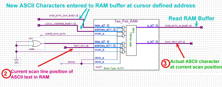
ASCII characters are stored in RAM within the FPGA. While not essential,
we will use what is called dual ported RAM, so this RAM overlaps with the S100
bus RAM such that the S100 bus Z80 and the FPGA share the same RAM area (we use the
S100 bus Phantom line to avoid conflicts). This makes accessing the FPGA
RAM easy as anything read or written to the S100 bus RAM will also occur
on the FPGA RAM. The S100 bus RAM will be a window at 8000H to
8FFFH (or E000-EFFFH for
VGA_TTY.Z80). If we place a character (say 33H) at 8000H/E000H in the S100 bus RAM, it
will also be placed at position 0H of the FPGA RAM.
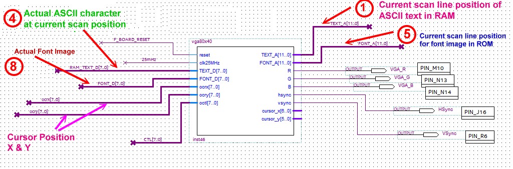
Lets follow the display process.
1. The VGA80X40 module outputs the current scan position (11 bits), that
the
video signal it is 'at'.
2. This position is fed into the dual ported RAM.
3. Whatever ASCII character is at this RAM position is passed out
4. This ASCII text is fed to the VGA80X40 module
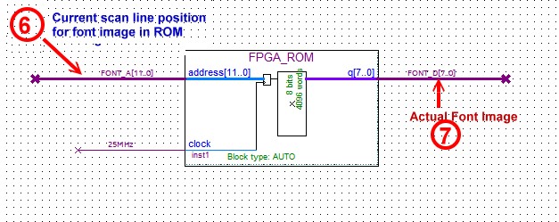
5. The corresponding FONT address (11 bits) is sent out.
6. This adders is sent to the Font lookup table in the FPGA ROM
7. The actual FONT image comes from this ROM
8. The FONT image is passed to the VGA80X40 module for display on the screen via
the RGB signals.
Totally independently, a cursor is displayed on the screen. Its position is
defined by two 8 bit inputs. Its important to appreciate that the cursor
and character images are not connected. The user is responsible for
maintaining both separately.
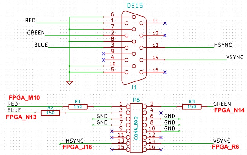
Here is the hardware VGA Display connection/connector.
You will note that we use the same 8X2 pin connector we use on a number of our
previous VGA boards (e.g. the
16 bit VGA MS
Compatible board). This allows you to use a DB15 VGA socket at the
back of your S100 system. Of course if you don't mind connection the VGA
cable to the top of your FPGA board you could use a DB15 socket directly.
Everything else is programmed into the FPGA!
This circuit is one of the components of the
FPGA Board Shield #1 board.
As is almost always the case with simple FPGA circuits like this the are many
ways to program the chip. In this case I have opted to write the VGA.bdf code diagrams "long
winded" to make it easier for beginners to understand.
First make a new sub-folder within your Quartus programs, call it "VGA".
Download the VGA.zip file (see below) and expand it into this folder.
Launch Quartus and load the VGA.qps
and VGA.bdf files.
Spend some time studying the layout of the VGA.bdf file.
If you reassemble/modify the VGA.bdf file the lat0-12.HEX
file must be present (as it is in the .zip file above) in the same directory.
Both the FPGA dual ported RAM and FPGA ROM modules are from the Quartus IP
folder (Tools/IP catalogue/Library/Basic Functions/On Chip memory). If you
play around with the ROM be sure you have the third dialog box point to the
lat0-12.HEX
file. The RAM module can be initialized to 20H's
(Spaces) with
RAM20H.HEX.
When you think you have the "gist" of it, from your PC, program your FPGA module
on the V2 FPGA Prototype board with the FPGA Board Shield #1
board attached and setup as you did for the Pong program.
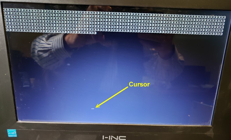
When you run the program nothing will appear on the VGA screen.
From your Z80 monitor enter F8000,8300,33
The top few lines of the VGA screen should show 3's.
From your Z80 monitor enter:-
QO68,20
QO69,20
The cursor should appear on the screen.
Here is a picture:-
Next download the Z80 demo program
FPGA_VGA.ZIP and expand it on your PC. You
need to XModem the
FPGA_VGA.COM or
VGA._TTY.COM files to your S100 system.
Use the Z80 Monitor "X" command with an address of 100H.
There are a number of other ways to do this, but in the end you must end up with
the above
FPGA_VGA.COM
or
VGA._TTY.COM files
at 100H in your S100 bus system.
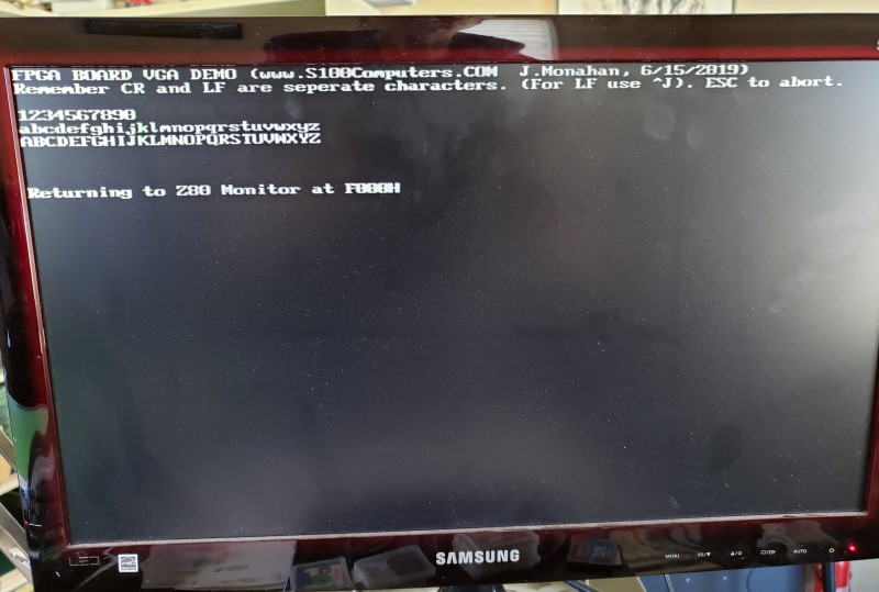
When done, again from your Z80 monitor enter:- G100
The program will signon on your Propeller Console IO board and the VGA monitor.
Enter text from your console, it should appear on both the Propeller Console IO
board and your VGA display.
Here is a picture:-
While the code is capable of 80X40 lines, I find on my (old) VGA LCD display
terminals it's best to stick to, at the most, 80X36 lines.
You might want to play around with the value of the 3 resistors for the RGB
color signals. While the original
Pong circuit used 150 Ohms, higher values such as 260 Ohms may be better to
reduce the character brightness.
Note, you can also set the text color with the Boards dip switches (SW1, SW2, SW3).
White or Green text on black seems best.