A Basic FPGA PONG Game Code Example.
One thing FPGAs are good at is doing video circuits. Simple video displays
like a VGA display are essentially a series of counters. Here we will use
our V2 FPGA Prototype board to send video to a
VGA display. The example we will use is a single paddle PONG game - a
classic game from the late 70's. The only hardware need is an output to
the VGA monitor (5 lines) and two lines of input for the paddle control.
Here is a short video of the output.
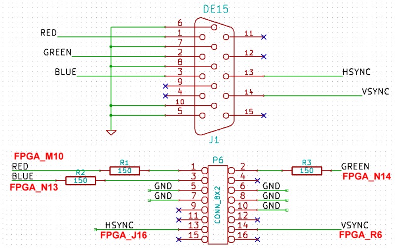
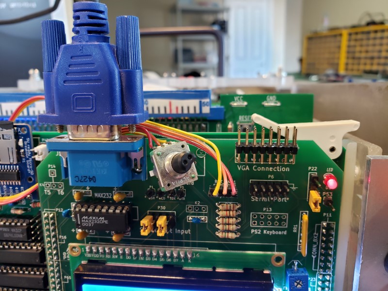
Here is the hardware VGA Display connection/connector.
You will note that we use the same 8X2 pin connector we use on a number of our
previous VGA boards (e.g. the
16 bit VGA MS
Compatible board). This allows you to use a DB15 VGA socket at the
back of your S100 system. Of course if you don't mind connection the VGA
cable to the top of your FPGA board you could use a DB15 socket directly.
There are numerous examples of actual FPGA code for a VGA display on the web.
Many are somewhat elaborate and hard for a beginner to understand. In the
end I found the example on
FPGA4Fun.com a "PONG Game" to be an excellent introduction. There are two
parts. Generating the video output and imputing the paddle position. The FPGA
code is in Verilog in this case. Since we will be using a
.bdf
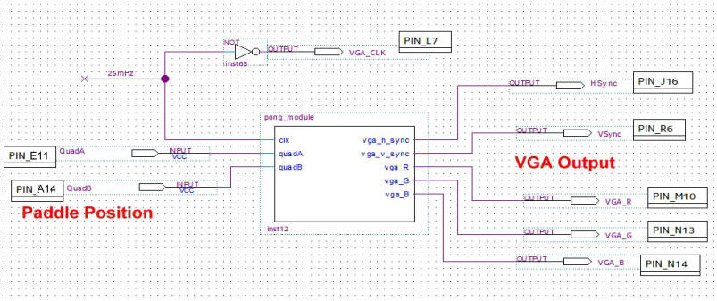
file we will take the
pong_module.v
file (see below) and from Quartus File menu
"Create a Symbol File from the Current File". This give us the core of our
PONG.BDF
file:-
As is almost always the case with simple FPGA circuits like this the are many
ways to program the chip. In the above
pong.bdf
file I have left in much of the S100 bus interface in case you wish to elaborate
on the program later.
For a standard VGA display VSync
is 60 Hz and HSync
is 31.5 KHz.
Starting with a clock of 25 MHz the following Verilog code gets us there close
enough:-
We generate the HS and VS pulses from D flip-flop (to get glitch free outputs).
reg
vga_HS, vga_VS;
always @(posedge clk)
begin vga_HS <= (CounterX[9:4]==0); // active for 16 clocks
vga_VS <= (CounterY==0);
// active for 768 clocks
end
The VGA outputs need to be negative, so we invert the signals.
assign
vga_h_sync = ~vga_HS;
assign vga_v_sync = ~vga_VS;
We generate a 25 MHz clock by modifying the Quartus supplied IP library PLL01.
That library allows up to 4 clock outputs from our 50 MHz board clock input.
See the top of the PONG.BDF file. You
can check you are getting this frequency on P65,pin1.
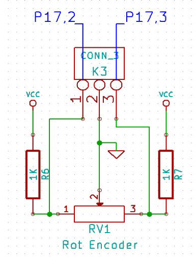
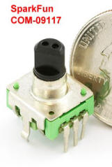
Next we need to add code to take care of the paddle position. Again there
are many ways to do this. The nicest is to use a "Quadrature Decoder " rotary
encoder switch such as this one from SparkFun (#09117).
These encoders provide two outputs that define relative position clockwise or
counter-clockwise.
Please see
here for details
(Incremental encoders). This picture from Wikipedia says it all.
As you turn the knob you control the left/right movement of the paddle.
Watch the above video to see the control in action.