| Jumper | Function |
| JP5 |
Normally closed. Generate the S100 bus MWRT signal on this board when it is active. |
| JP4 | Normally closed. Generate the S100 bus 2MHz Clock signal on this board when it is active. |
| JP23 |
Normally closed. Pulls SIXTN* high |
| P11, P12 | Normally not used.
Used to pull-up NMI* & INT* if board is a bus master |
| JP7,JP8, JP9,JP10 | Normally all open unless the board is a bus master. |
| JP13 |
Normally open. Used if board wants to utilize the S100 bus
Phantom Line |
| P26 & P29 |
+5V and GND posts for board patch area |
| JP6 |
Normally closed. Allows code in CPLD to lower the S100 bus Reset
line |
| JP1, JP2,
JP3 |
IEEE-696 GND lines, normally open. |
| P37 |
Connector to attach ribbon cable for patch area if required |
| P28 | Normally
1-2, Defines how board utilizes the S100 bus Reset signal |
| K1 |
Normally 2-3, Reset the CPLD |
| K2 | Normally
2-3. Source of board 1.8V power supply. |
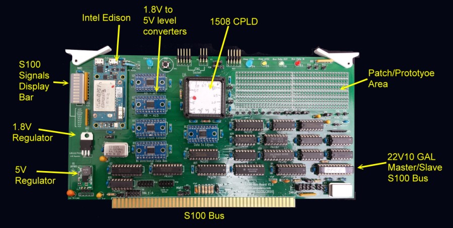
| P6 or P5 | CPLD JTAG programming socket.
(For Rockfield Research 1508 programmer use P5. Pin 1 is bottom left). |
| P16,P21,P20 |
Jumpers for spare CPLD pins, normally unconnected. |
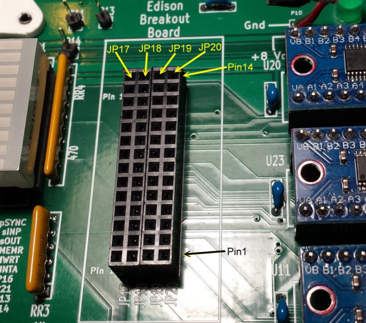
| P24,P17,P18,P19 |
Unused Edison pins (level shifted to 5V) |
| P8 |
S100 Bus TMA line to activate board. Normally 1-2 (or 3-4)
closed. |
| P15 |
Jumpers to patch connections to extra S100 bus lines. Normally
all unconnected |
| P22 |
Inputs from S100 bus Interrupt vectors. Normally all open. |
| SW1 |
This is a mini push button switch. Push once to stop the monitor
action. Push again to restart. (Check orientation at R5) |
| Other Jumpers |
These jumpers are posts to connect experimental circuits in the
patch area to other parts of the board. |


.jpg)
