The S-100 Box and Power Supply
S-100 boxes and card cages come in many sizes and shapes.
The IMSAI box is a classic of the early designs. However these systems fail at
high CPU bus speeds because of their simple non-terminated motherboards. I decide to make my own
S-100 box.
The first question I had was how big a box do I want the final computer
to be in? Did I want to include hard disks, floppy drives (8" and/or 5" drives)
and their power supplies. After a long decision I decided on a fairly
large box
for the S-100 card cage and its power supply and room for one 5" hard drive. This would
be the basic functional system. To load and save software a separate box with its
own power supply would contain two 8" floppy drives, one or more 5" drives and later
if needed (see here), further hard disks (probably modern IDE interfaced drives). I wanted
go with a standard metal box structure so in the end decided on a 7" high, 17" wide,
32" deep aluminum box. I obtained this box from
Mouser Electronics. You
might also consider the more standard 19" wide boxes as this as I later noticed
will allow you to place the hard disk flat beside the S-100 card cage instead of
on it's side as we shall see in my case. As we shall see we will only be using
the sides and bottom of this box since we will have to have very fancy front and
back panels custom cut (see below). My main reason for the smaller tight box
dimensions was that I wanted it to take up as little space as possible on my main
office desk. The box was all aluminum with many holes and bolts
showing as I attached the motherboard and power supply.
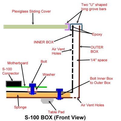
I then "double hulled" it by having a second "U" shaped box
made. I had this made out of sheet steel by an outfit called
ShortRun Pro. They will cut any shape you
order and also paint it. By fitting one "box" within another I have a very professional
look. The trick was finding a way to secure the inside box within the outside box.
On the inside bottom of the outer 'U' shaped box I put a layer of sponge. This allowed
the inside box to sink into the outside box. All the nut heads securing the motherboard
etc sunk into the sponge. I secured the two together with 4 bolts. The problem was
what to do about the sides. I took my clue from what Altair did with their box.
I picked up a strip of metal at a local hardware shaped as shown in the picture
below. By epoxy gluing it to the outside edges of the inner box and making a grove into which
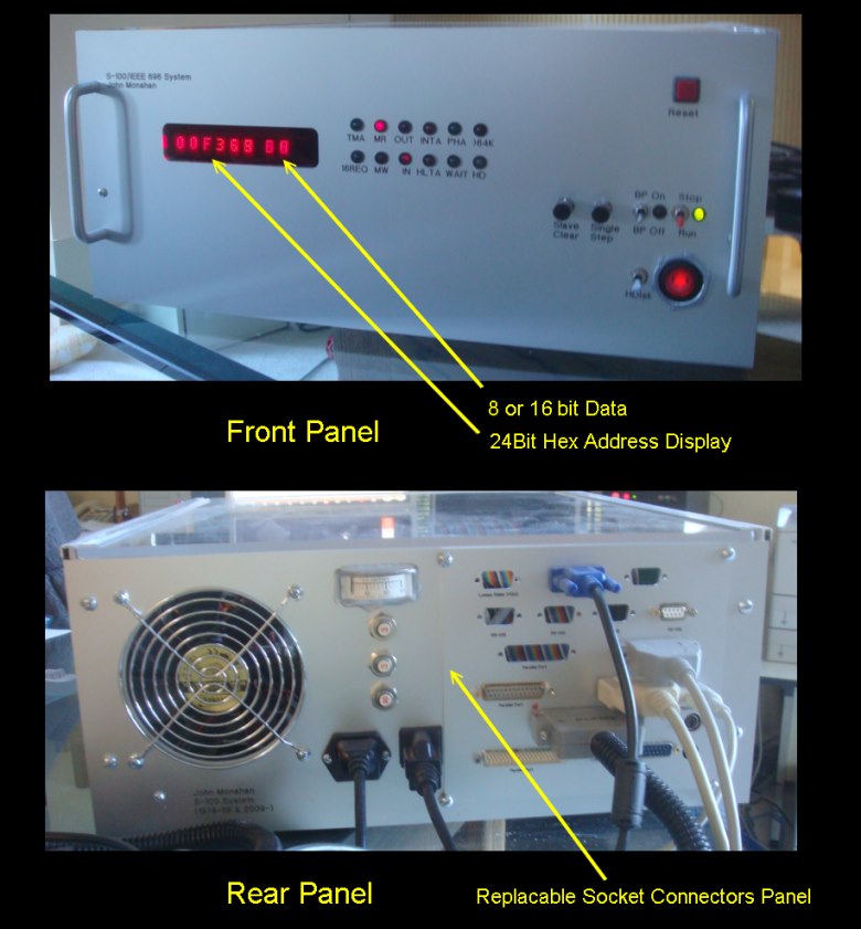
the outside box slid, no ugly screws are needed. Both the front
panel and back panel have gone through
a number of iterations. In each case I had aluminum panels cut by an excellent (and
reasonable priced) group called
Front Panel
Express.
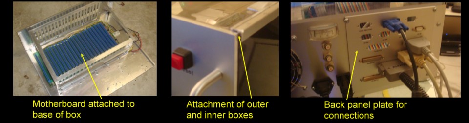
They do great work and are fast. For the back I had a panel attached to a large
square hole with many DB9,25, keyboard, video, etc. slots. Since my needs
change over time I find it is easier just to have made this sub-section and bolt
it to the main back panel. The front panel housed a window for my front panel
display and various switches which I will describe later. Here are some pictures:-
| |
 |
| |
|
| |
 |
The Card Cage
In spite of searching a lot I could not find a 22 slot S-100
card cage on the web and elsewhere. I did come across a Northstar box and card cage
on eBay but it was too small for my long Godbout 22 slot motherboard (see below).
In the end I decided to make my own card cage out of common " L" shaped rods of
aluminum cut and assembled to support the card guides as shown above.
The card guides are attached to the frame by drilling
holes and popping the card guides in place. It's important to make sure they are exactly
aligned with the S-100 edge socket otherwise the card will not be vertical and make
a reliable connection with the bus. These card guides I obtained years ago from
a surplus electronics parts store. You can get them today from companies like Mouser.
Make sure to get guides that do not use up too much of the boards real estate as
some boards have components close to the edge of the board and so will not slide
easily into the bus.
The Motherboard
If you are going to
run your CPU at low speed (~2MHz) the type of motherboard is not too important.
If you want to have a reliable high speed system (say >6Mhz) you definitely will
need a good motherboard. Many were made for S-100 computers. You can even
I suppose make your own simply by connecting a number of 100 pin connectors
available from companies like Mouser or DigiKey or
Vector.
I have had very good success with a 22 slot TEI Motherboard.
The
Godbout motherboard is very similar except that it has 20 S-100 slots
instead of 21. This board is extremely well made with a thick
backing, a well grounded back-plan and multiple attachments to attach the +8, +16
and -16 power lines along the length of the board. The board has electronics to
minimize noise and cross talk on the address, data and control lines on the bus.
The schematic for this circuitry is shown
here. It is important to attach the motherboard properly to the above metal
box/card cage. There are multiple attachment screw points under the board.
make sure to utilize them all. You do not want the board flexing as you
insert and remove S-100 boards. The figure shows the motherboard in place. Note the use of heavy
power line wires. Many S-100 boards take well over 1 amp each to run. With 22 cards
in place the 8V line can be running well over 25 amps. Heavy copper wiring is essential.
Also to be on the safe side each line needs to be properly fused. I used 'pop-out'
fuses since on more than one occasion I had a short.
The Power Supply
The S-100 bus is a little
unusual in that unlike many other computer busses the power supply to the cards
is distributed to voltage regulators on each card. There is no regulated +5
volts line for example. Whole books have been written on power supplies. Fortunately
for the S-100 bus the power supply can be relatively simple. What is needed is +8
volts on pins 1 and 51, +16 volts on pin 2 and -16 volts on pin 52. Here is a typical
power supply schematic.

The above are the desired voltages. Because each S-100 board
has its own voltage regulator (or Zener diode), there is a wide tolerance as to
voltage values that can be used on the bus. For the 8 volt lines for example,
you can normally go down to about 7.5 volts or up to 10 volts -- although the regulators
on the boards get quite hot at the latter values. Over voltage values on the
+16 and -16 lines are typically more of a problem because many boards use a
Zener
diode with a lower power dropping resistor which can overheat. Also if the
voltages on these lines are above specs check the voltage tolerances for the power
lines filtering capacitors on each board. Recently I had an old Godbout memory board
capacitor actually go on fire because the voltage was above the boards rating.
Today there are two basic power supply systems you can use
for your S-100 computer system, "Linear power supplies" and "Switching power supplies".
In the old days all S-100 systems used only Linear power supplies. The above schematic
is an example of such a supply. These typically consisted of one large transformer
a series of diodes and a few large "can" type capacitates. Because each S-100 board
could take 1-2 amps, typical supplies were capable of supplying 20 - 30 amps on
the +8 volts line. The advantage was they were simple and cheap to build.
However they were cumbersome and heavy. 30 Amp power supplies like this weight 10
or more pounds!
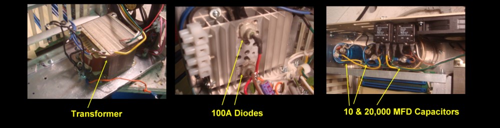
I started off putting a linear power supply in my
system. Apart from the large
transformer, the diodes should be capable of handling initial current surges of
100+ Amps. Large metal can type of smoothening capacitors are required. Here
are a few pictures.
In the end I decided
against using this setup for two reasons. First it took up too much room and second
I was unhappy with the transformer output voltage for the +8 volt line. It ended
up being about +10 volts. This would work, but the voltage regulators on the S-100
boards would run hot. I searched the usual web sources for a 20+ amp transformer
that would supply +8 and +/- 16 voltages. I could not find a reasonable candidate.
One way around this is to use a small common Japanese power supply converter that
converts the US 110 volts AC to the 100 volts the have in Japan and use this output
to feed the main power supply transformer. However this arrangement uses up
still more real estate in my computer box.
Switching
Ppower Supplies.
These are common these days. Every IBM-PC type computer in the world has one. Unfortunately
these power supplies only put out +5, and +/- 12 Volts. We need higher voltages
for the S-100 buss. Fortunately there are more specialized power supplies available
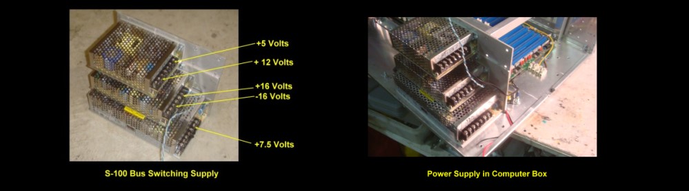
to handle these voltages. I ended up going with a number of power supplies
from a group called Mean Well available from many common
suppliers, for example Mouser. For the S-100 8 volt line you can use either their 16A, 9V supply
(S-150-9) and adjust it down to ~8.5 volts or use their 27A 7.5V supply
(S-210-7.5) and adjust it up to ~8 volts. I find all the voltage regulators I have on my boards work fine with
7.5 Volts. They run cooler at this voltage too. Now since this supply
is capable of delivering significant currents I wanted to have a safety net of 3
fuses on the 3 power lines. These are the resettable pop out fuses. I currently
am using 20 amp fuses on the 8 Volt line and 3 Amp fuses on the 16 volt lines. The
good news is we don't need large filtering capacitors any more.
Mean Well also have a number of 15V (which are adjustable up 10%) for your +/- 16V
lines. 3 Amps on each is usually more than enough. For the +/- 16V supply I use
their
T-60C,
adjusting the 15V supply upwards.
Mouser also supplies PSU's like these. Their
TDK LS50-15
supplies
+15Volts (only), at over 3 Amps. Their
MeanWell RSP-200-7.5
can be adjusted up to 8 volts and can deliver 26 Amps! There are
many other suppliers of these units all available on the web.
Just for my own information I have a small 25 amp current meter in line
on the 8 Volt. This is not really necessary, but it is nice to know how much current
your computer is using with different configurations. By the way, some people
have changed their S-100 system power supply to put out 5 volts on the 8 volt line
and +/- 12 volts on the 16 volt lines and remove the voltage regulators on all cards.
This does seem to work fine though it is a little bit of a pain when you collect
S-100 Boards in that you have to modify each card. Also be absolutely sure you don't
put these cards back into a standard +8 volt S-100 system. The advantage is you
can utilize the above common IBM-PC type power supplies.
Finally a word of caution. The 8 volt power supply line in
these systems is capable of delivering considerable current. Its can be a mini
arc welder -- be careful.
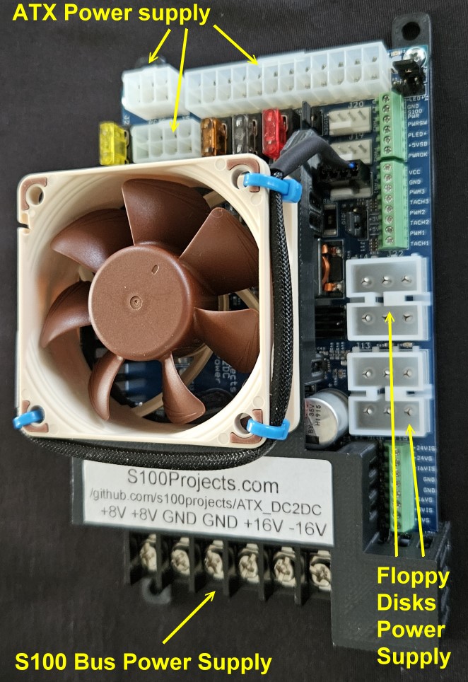
An PC ATX Power Supply.
More recently Jefferey Wilsom has designed and produced
a very nice compact S100 bus power supply that
utilizes the common PC power supplys.
The "ATX DC2DC power supply board"
uses a 550W or greater ATX PC power supply (PSU) to generate the common S-100
Bus voltages (8v, +16v and -16V voltages) and power for two Floppy disk
drives.
Please see
here for
more information about this power supply..
A S100 Bus Motherboard and Power Supply
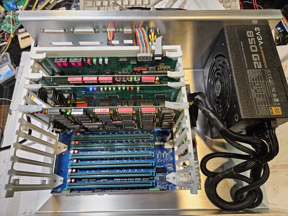
More recently Jefferey Wilsom has also designed and produced
a very nice compact S100 bus motherboard (with active termination).
It utilizes the common PC ATX power supplies for all the S100 bus voltages.
Jeff also supplies board guide rails etc.
For the actual computer box you can utilize some of the common PC boxes (the
motherboard holes fit most PC boxes), or you can have a simple custom metal
setup I have here .
which allowas easy access to boards.
For more information please see
here.
Other pages describing my S-100
hardware and software.
Please click
here
to continue...
This page was last modified
on
03/04/2025