A LCD Display FPGA Code Example.
This
circuit example adds a very basic LCD Display to the
FPGA Prototype board. It assumes the
user is familiar with the very common "1602 16X2 LCD Display modules". Most
commonly found in Arduino board circuits.
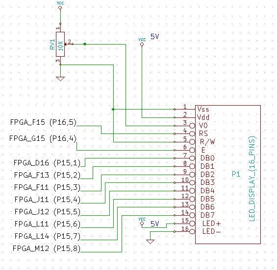
The actual hardware on the board consist of nothing more than a 16 X1 pin
connection and a variable Pot (10K, to adjust the display intensity).
Here is a schematic
and picture.
Interfacing this LCD display to display ASCII characters is simple. We will use
an 8 bit data interface and use the S100 bus Port Write strobe for the LCD "E"
enable pulse.
There is one slight complication however. This and most other similar LCD
displays need to be first configured upon power up. In other words before you
can send any ASCII characters to the display you need to send (in this case), at least 4 bytes
to its "Configuration Register"
before sending ASCII characters to its "Data
Register". There are numerous ways the (two lines)
of characters can be displayed. Here is a list of a
few:-
There are more than this, but this should give you a feeling of how the LCD
display is controlled. There are two "Registers" within the unit. When the
RS
pin (pin 4) is low any data sent to the unit is
interpreted as an instruction
(see above). When
RS is high any data sent to the unit is understood to be a
display character. You can go back and forth between these two registers
any time.
We will "power up" the LCD unit to display a single line, 16 characters
across. The cursor will be on the RHS and as each character in entered the
characters will scroll leftwards one character. At any one time the last 15
characters entered will be displayed. For this we need to send the following
bytes to the unit with
RS low.
38H ;Set 8 bit mode
0FH ;Display On, Cursor on
8FH ;Position cursor on RHS.
07H ;Shift left after each character addition
If we were building a classical S100 bus/LCD
interface we would program our Z80 etc. CPU to send these commands upon power up.
With our FPGA we can easily incorporate such things into the FPGA. We will
write a small Virlog module (LCD1602.v) which sends these bytes to the LCD
display unit upon power up. We then convert it to a
.bdf module and splice
it into our LCD_Display.bdf file. This file is available at the bottom of
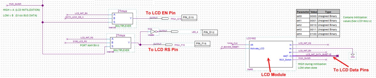
this page. The key section is displayed here:-
The actual LCD_Display.bdf layout is fairly
straightforward. If you used
our UART.bdf code you will see that that this file starts from that code.
The only complication is that we need to switch the 8 bit data input lines to
the LCD display from the LCD1602 module to the 8 bit data line from the S100 bus
port 68H after the
initialization. We do this with a 2:1 MUX. When
S is
high the data to the LCD display data comes from the LCD1602 Module. When S is
low the LCD data comes from the S100 bus (Port 68h). The last line
in the LCD1602.v code switches the lines over.
Once Initilized any 8 bits of ASCII data sent to
port 68H by the Z80 appears on the
LCD display. Should you wish to switch over to the LCD module
RS register you set bit
0 of S100 bus port 69H
Low. You can later set
it high again and
output characters to the LCD display.
The FPGA also has circuits to read the last byte sent to the LCD display by
inputting from S100 port 68H, (QI69).
When you do this the value will not only appear on your console but also the FPGA
board LEDs will also display the value. You can at any time read the status of the LCD RS
line by inputting bit 0 of the S100 port 69H.
Here is a simple Z80 master monitor session
QO68,33
QI68 00110011
QI69 00000001
This is a very simple example of using our Cyclone IV to for a LCD display.
Please study the files below to understand completely what is going on.
Bugs
There is a minor bug in the program in that if you reinitilize the LCD display
(ie. upload the code again) without a power down the LCD display gets confused.
(More code needs to be added to reset the LCD upon reset).
FPGA_LCD_DISPLAY.ZIP
LCD1602.v
This page was last modified on
11/04/2018