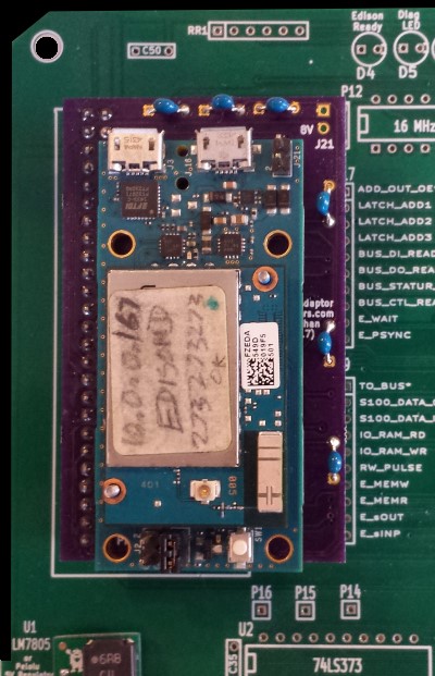

The Intel Edison TXB Adaptor Board.
The Intel® Edison is an ultra small computing platform that was first
announced in March 2014 and after some changes produced in September 2014. The Edison packs a huge amount of tech goodies into a tiny package while still
providing the same robust strength of your go-to single board computer. It is
driven by the Intel® Atom™ SoC dual-core CPU and includes an integrated Wi-Fi,
Bluetooth LE, and a 70-pin connector to attach a veritable slew of shield-like
“Blocks” made by the likes of
SparkFun which can be stacked
one on top of the other.
The Intel® Edison packs a robust set of features into its small size, delivering
great performance, durability, and a broad spectrum of I/O and software support.
The board's main "system on a Chip (Soc)" is an Intel Atom "Tangier" (a
Z34XX) that includes two Atom Silvermont cores running at 500 MHz and one Intel
Quark core at 100 MHz. The latter runs the ViperOS Real Time Operating System
(RTOS)). The unit has 1 GB of RAM integrated in the package. There is also 4 GB eMMC
flash on board, Wi-Fi, Bluetooth 4 and two USB controllers. The board has a special
Hirose "DF40", 70-pin dense connector with USB, SD, UARTs and many GPIOs pins.
In its default mode it runs Yocto Linux. Intel supplies development support for
the Arduino IDE, Eclipse (for C, C++, and Python).
The Intel Atom itself was released in 2008. It was the
brand name for a line of ultra-low-voltage IA-32 and x86-64 CPUs, originally
designed in 45 nm CMOS and later using a 32 nm process. The Intel Atom
today is mainly used in netbooks, nettops and embedded applications.
All Atom processors implement the x86 (IA-32) instruction set and except for
very early versions they support the Intel 64 instruction set as well. However
the are issues with some versions supporting the 64-bit versions of Microsoft
Windows and Ubuntu or Debian GNU/Linux.
The performance of a single-core Atom is about half that of a Pentium M of the
same clock rate.
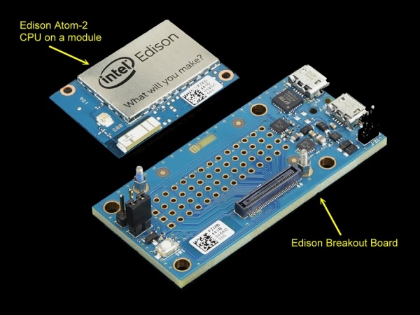
The Edison Atom-2 module connects to the outside world via a very
(small) specialized "Hirose 70 pin connector". It is simply not practical to hand solder
this connector to a printed circuit board. The pin spacing requires a special machine to do so.
Fortunately Intel supplies a special "breakout board"
that brings the relevant GPIO pins out to a 4X14 array of jumpers spaced
0.1" apart (see above). This is the Edison CPU board will work with here.
Before working with the Edison module you should read about its many features.
Both Intel (see
here) and SparkFun (see
here)
provide excellent write-ups. There is also a decent book "Programming the Intel
Edison" by Donald Norris (Mc Graw Hill) worth reading. However by far the
best information can be obtained (here)
in a series of articles by Harry Fairhead. Later for questions, you
can use the
Intel Edison Forum.
To use this module in any S100 bus system (or indeed with many homebrew
circuits), there is one major issue. All input and output to the
Edison general purpose I/O pins (GPIOs) must never exceed 1.8 volts.
So you can never directly interface this unit to a 5V 74LSxxx chip for
example. Even a momentary exposure to 5 volts will "burn out" the
Edison module.
We need a "Voltage-Level Translator" to bridge the interface. There
are a number of possible choices. In the past I found the common Ti
TXB0108 8-bit Bidirectional
Voltage-Level Translators worked well.
Unfortunately these chips only come in a SMD format. While not
difficult to solder as such, for convenience for most users, we use these chips in a
20 pin "adaptor" DIP format on our
Edison and
Edison II S100
boards. As you can see these adaptors take up a lot of space on a
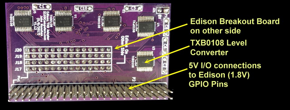
board. What would be nice would be a small Edison "TXB
adaptor board " that has these the five TXB0108's surface mounted
tightly beside the Edison unit and this combination plugs into any S100 bus
board (or other circuit) via a standard 2X25 pin connector with
0.1" spacing's. This Edison TXB Adaptor can then be moved around from
board to board as a single unit. Since the Edison is programmed
via a WiFi link, this allows for a very useful and flexible unit.
While this adaptor has a number of potential uses, the main driving force
for me is to use it on a (later to be announced, 4GB
S100 bus OTT RAM board utilizing the 1GB onboard DRAM of 4 Edison modules).
The Circuit.
The actual circuit for this board is in fact
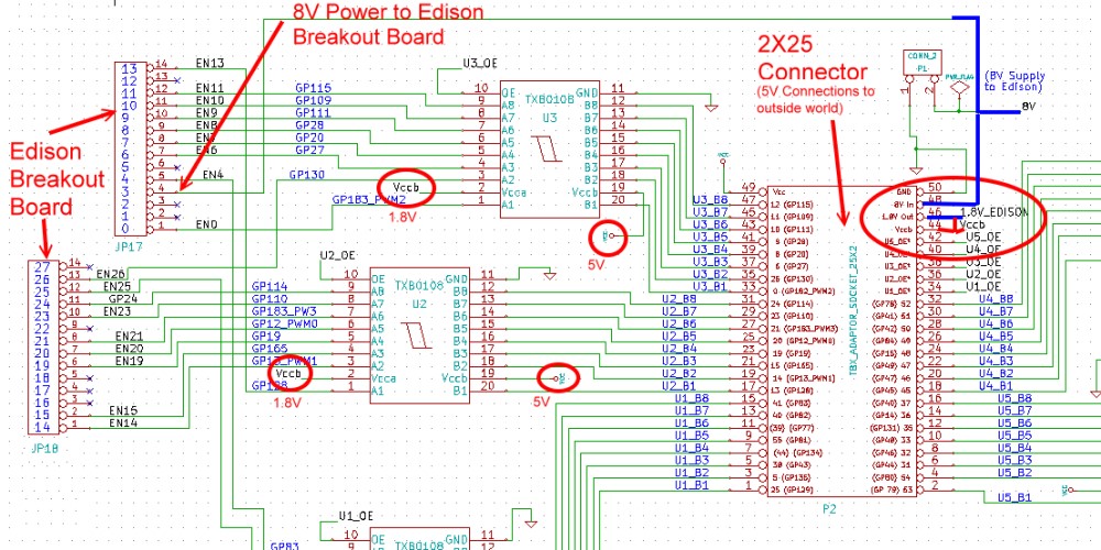
quite simple. Each of the Edison GPIO pins go directly to 5 TXB0108 8-bit Bidirectional
Voltage-Level Translators. Here is an example:-
The Edison breakout board accepts its main (8V-14V) power supply through its
JP17 pin 4. There actually is no need to use the J21 jumper.
(This is something I did not know when doing the
Edison &
EdisonII
S100 boards). The Edison breakout board also supplies a 1.8V output
from its J19 pin 2 connector (not shown above). We bring
this pin output to pin 48 of the 2X25 0.1" P2 connector (see above).
Normally this pin would be connected to pin 44 of the same connector thereby
supplying 1.8 volts to all 5 TXB0108 level converters on the board.
The other side of these level converters obtain 5 Volts from pin 49 of the
P2 connector. This would normally be supplied by the external 5V
circuit this board would interact with. Each of the 5 level converters
also have an output enable pin (pin 10). When low the level converter
outputs are active. These can be individually activated through pins 34,36,38,40
& 42 of the 2X25 P2 connector. For many applications they would be
always on and thus just grounded.
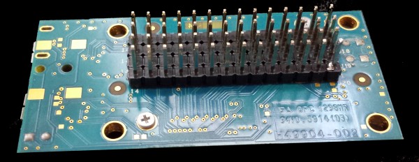
The real trick with this board is having it such that the overall high of
the board on an S100 bus board is such that the resulting combined board
will not require more than one S100 bus card slot. We do this by
utilizing pin connectors such as those from Jameco #2168173 cut to size.
Here is a picture:-
This board is then soldered into the actual adaptor board as shown here and
trimmed to the surface of the board.
This Edison TXB adaptor can then be used to directly interface with the
standard 5V TTL logic we have on our typical S100 boards. Here is an
example.
The board can either be directly soldered to the S100 board or reversibly
connected via a 2X25 pin connector. The former situation will not
utilize more than one S100 bus card slot.
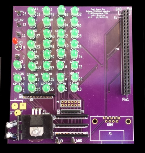
An Edison-TXB Adaptor Test Board.
I found in the past that sometimes my soldering of the
TXB0108 8-bit Bidirectional
Voltage-Level Translators was not always 100%. An unconnected Edison
pin can wave havoc with your application and is sometimes difficult to
detect since the standard TTL logic probes do not work. I therefore
constructed a companion Edison-TXB Adaptor test board. Using a simple
Edison C diagnostic program run on the Edison via its WiFi
connection, any LED not flashing indicated a bad connection.
Here is a picture of the prototype test board.
The EdisonTXB Adaptor board is plugged into the socket on the RHS. Starting
on the bottom right (GP_45) and going upwards each LED should flash briefly
unless the is a soldering/connection error. The relevant Intel IoT
Development C program is at the bottom of this page.
In my hands using the default Intel OS software, the Edison pins GP77
and GP134 appear inactive. The pins GP82 and GP12 seem to work in
input modes only. The remaining 38 pins seem to work fine in output
mode. I use the following core Intel IoT Eclipse Platform C code:-
........
case 40:
// GP82 Seems to only work as an input)
case 20:
// GP12_PWM0 Seems to only work as an input)
pin[i] =
mraa_gpio_init(i);
// Set as data inputs
mraa_gpio_dir(pin[i],
MRAA_GPIO_IN);
mraa_gpio_use_mmaped(pin[i],1);
// For fast I/O
break;
default:
pin[i] =
mraa_gpio_init(i);
// Default all outputs, initially HIGH
mraa_gpio_mode(pin[i],MRAA_GPIO_STRONG);
mraa_gpio_dir(pin[i],
MRAA_GPIO_OUT_HIGH);
mraa_gpio_use_mmaped(pin[i],1);
// For fast I/O
if (pin[i] == NULL)
{
fprintf(stderr, "MRAA couldn't initialize GPIO %i\n",i);
break;
};
........
Realizing that a number of people might want to utilize a board like this together with a group of people on the Google Groups S100Computers Forum,
a "group purchases" will later be opened. This "order" is currently
closed.
The links below will contain the most recent schematic of this board.
Note, it may change over time and some IC part or pin numbers may not correlate exactly with the text in the article above.
Intel Edison
Linux Install Package to run from Windows (64 Bit) ( v2016.1.002
5/25/2016)
WinSCP download for Windows (64 Bit) (v5.8.3
5/26/2016)
Edison TXB
Adaptor Test Program
(v1.0 10/23/2016)
Other pages describing my S-100 hardware and software.
Please click here to continue...This page was last modified on
10/23/2017


