
| Home | S-100 Boards | History | New Boards | Software | Boards For Sale |
| Forum | Other Web Sites | News | Index |
20mA Current Loops - Introduction
Standard high-current TTL or
LSTTL drivers can be used over relatively short distances for
communications. However, slight changes in the ground voltage reference
or a volt or so of noise on the link can cause a lot of noise in such
links. A better way was looked for.
A differential line using a pair of wires was used, in which the
variable in positive logic is on one wire and in negative logic on the
other wire. If one is high, the other is low. The receiver uses an
analog comparator to determine which of the two wires has the higher
voltage, and outputs a standard TTL signal appropriately. Then if a
noise voltage is induced, both wires should pick up the same signal and
cancel each other out. This is the basis of the well known RS-232
(and later RS-442) IEEE standards. Much has been written on these
protocols. See
here
to get started.
Less well known however is an earlier communication method first thought
about back in the days of the telegraph the 20mA current loop.
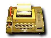
Perhaps the most famous user being Teletype Corporation's ASR33
"Teletype".

The 20-mA current loop
consisted of just a pair of wires connected to a "driver" and "receiver" so as
to implement an electrical loop through both. A true corresponds to ~20 mA
flowing through the loop, and a false corresponds to no current or to 20 mA
flowing through the loop in the reverse direction. A current, rather than a
voltage, was used because it could be interrupted by a switch in a keyboard and
that could be sensed anywhere in the loop. A current was also used because in
older equipment the 20-mA current loop could be used to drive a solenoid, and a
solenoid is better controlled by a current than a voltage to get faster rise
times. The current was set at 20 mA because the arc caused by this current will
keep the switch contacts clean.
20-mA current loops had problems however. A loop consisted of a current source
in series with a switch to break the circuit, which in turn was in series with a
sensor to sense the current. Whereas the switch and sensor were obviously in two
different stations in the circuit, the current source could be in either
station. A station with a current source was called "active", while one without
was "passive". If two passive stations, one with a switch and the other with a
sensor, were connected, nothing would be communicated. If two active stations
were connected, the current sources could cancel or destroy each other.
Therefore, one station had to be active while the other was passive, and one
must be a switch and the other must be a sensor. While this is all very
straightforward, it was an invitation to trouble. Also, note that the voltage
levels were undefined. Most 20-mA current loops worked with voltages like +5 or
-12 or both, which were available in most communications systems; but some,
designed for long-distance communication, utilize "telegraph hardware" with
voltages in excess of 80 V. Therefore, one did not connect two 20-mA current
loop stations together without first checking the voltage levels.
Finally, these circuits generated a fair amount of electrical noise, which got
into other signals, especially lower-level signals. The switch in such a
circuit generates noise that is often filtered by the sensor. Unfortunately this
noise was at frequencies used by 1200-baud lines, so the filter could not be
used in other places in a communications subsystem.
The circuitry for a 20-mA current loops today can be built with an
opto-isolators. These tend to eliminate some of the above issues. Nevertheless
a number of the early S-100 serial I/O boards had 20Ma loop options