We
normally build these S100 boards up in functional steps, we will start
with the sound circuit.
Insert U3, U2, U22 and jumper K5 connecting pins 1-2. Insert the three
dip switches. For MSX compatibility we will use ports
90H-9FH (video) and 48H & 49H (sound).
Switch settings (left to right) are:-
SW1 Closed,closed,closed,closed,open,closed, closed, open.
SW2 All closed.
SW3 Closed,closed,closed,open,closed, closed,open, closed.
Next insert U24, U31, U32, U6, U29, U5 and U11.
Insert U33, U4 and U8.
Insert the board into your S100 system and confirm you get a low to high
pulse when you input from I/O port 48H with your monitor.
Add U10, U34, U35 and if you are using them the two board speakers.
Jumper P1 1-2 and 3-4 (both vertical).
Add U18, U19 and U30.
Next carefully add U12 (the U9938), take care the pins are fragile and
hard to align with the socket.
Next add all remaining chips including the 4 RAM chips.
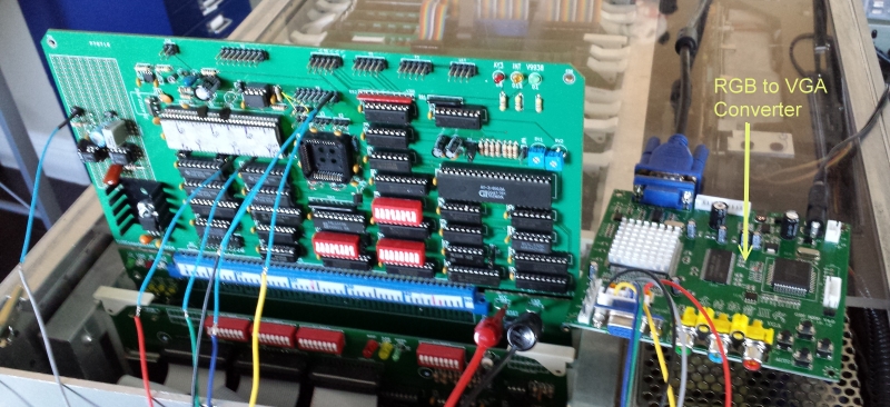
This is how the board should look:-
Test the board for sound with the very basic (two tones), use the
AY-DEMO.COM CPM program (see below).
Test the board video circuit use the very basic
VDP.COM CPM program (see below).
I am still looking around for two small speakers to fit on the board.
(If somebody locates one please let me know). Currently I'm using two 8
Ohm 10 mm round circuit board speakers from DigiKey (102-2493-ND).
However they are really too small and barely audible. This can be
fixed by adding a 10K ohm resistor across the speaker terminals on the
back of the board .
You are now ready to write software for this board!

.jpg)