DAZZLER Joystick Board
Theory Of Operation Terry Walker 10/5/2016 HISTORY
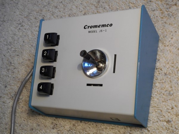
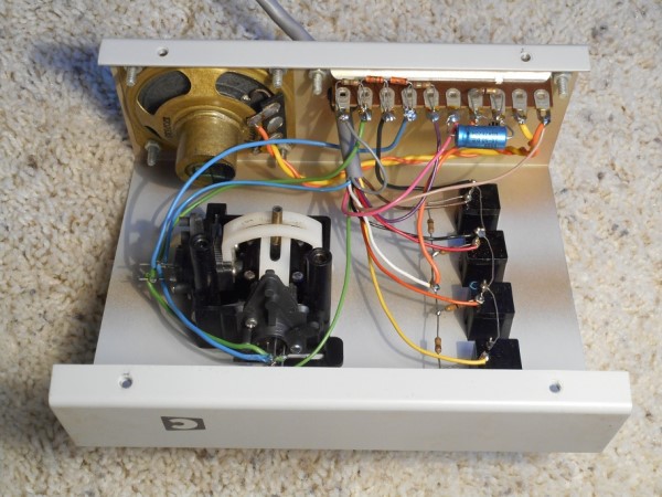
Here is the original Cromemco joystick unit JS-1 from the outside and inside.
This unit used a Kraft joystick similar to ones used in model airplane controls.
The inside picture shows the inside of the JS-1 unit. All of the internal
circuitry is point to point hand wiring between controls, terminal strips, and
the cable. This was typical of small products of the time period.
One objective of the new design is to eliminate all the hand wiring inside the
joystick box.
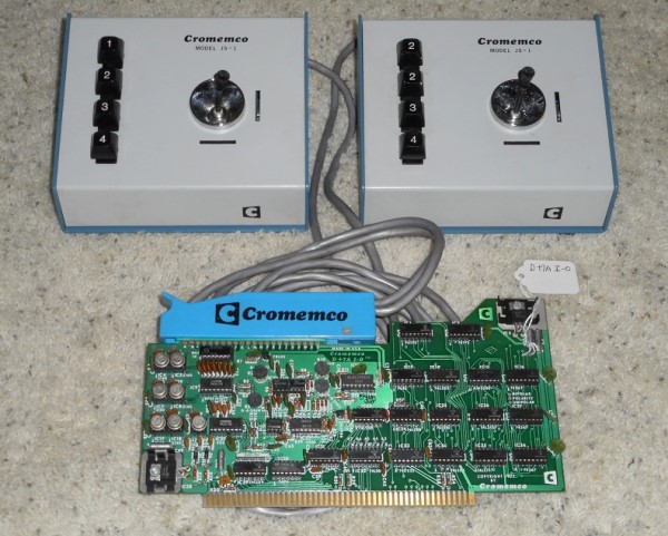
Here is a picture of a dual joystick pair together with the cable,
connector, and D+7AI/O PC board. The D+7AI/O board was made in the summer
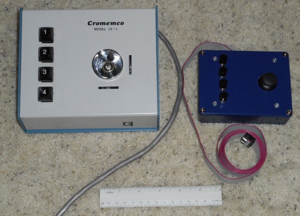
of 1977. The second picture is the origional and new joystick box side by
side.
Note that an entire S100 board is required to make the analog/digital I/O board
with 7 channels of analog in and out, and one 8 bit port of digital data in and
out. Most of the area is consumed by miscellaneous SSI logic required to
make the ADC control circuits for the analog input function. The joystick
interface on the TV Dazzler 2 implements a subset of this with 4 analog channels
in, 2 analog channels out, and one 8 bit input port as needed for the dual
joysticks only, taking only 4 ICs and part of a CPLD. Figure 4 shows a
comparison of the original JS-1 and its cable with the new joystick unit and its
16 wire ribbon cable. The new unit is smaller, lighter, and easier to make
but has the same electrical specifications.
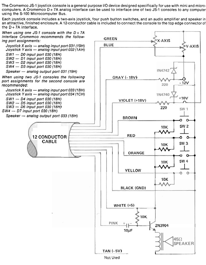
Here is a schematic of the original Cromemco joystick box JS1 used for playing
TV Dazzler games.
This was a simple design using a Kraft joystick as was commonly used for model
airplane control for the XY data input, together with 4 pushbuttons to select
program options and a built-in 2 1/2 inch speaker for sound feedback. The
speaker is a 45 ohm impedance unit made by Quam. Since the Kraft joysticks
did not go to either end of the control pots, but only moved over about the
middle 25% of the resistance range, the ends of the pots were connected to +10V
and -12V sources. This way the wiper voltage swing was about 4.5 volts.
The reason for the asymmetric voltage sources is unknown. Since the
D+7AI/O ADC input range was +/-2.55V, the pot output was a pretty good fit for
the ADC input range. The pushbuttons simply connected 4 of the digital
inputs of the D+7AI/O to ground, with 10K pull up resistors. Finally, a
simple emitter follower was used to drive a speaker from one of the D+7AI/O
analog outputs. The speaker had a 45 ohm voice coil resistance. The
2N3904 NPN transistor tended to have a current gain of about 150 to 200, so the
DC voltage on the emitter of the transistor was about +2V. Since the audio
input signal was AC coupled by the 10 UF capacitor the DAC output of +/- 2.5V
was a pretty good match for the signal excursion required at the transistor base
to give maximum audio output. The main problem with this circuit is lack
of availability of the 45 ohm speaker, and strong dependence of the bias point
on the transistor properties. Incidentally, both the schematic and the
internal construction of the actual JS-1 have the polarity markings on the 10 UF
capacitor backwards, the + end should be next to the transistor base terminal.
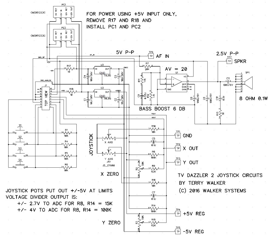
A NEW DESIGN
The new joystick presented here has the schematic shown here:-
Signal connections to the TV Dazzler 2 are done with a 16 conductor ribbon cable
and a mass terminated plug and header pair. Power to this unit is +5V for
the speaker amplifier and pushbutton pull up resistors, and +16V and -16V for
regulators to power the XY joystick unit. The pushbuttons connect to
ground as before, with 10K ohm pull up resistors to the external +5V source.
All circuitry is mounted on a single circuit board with no wiring inside the box
except for the mass terminated external cable connection.
The +16V is regulated down to +5V for use by the XY joystick top or right end,
and the -16V is regulated down to -5V for the XY joystick left or bottom end.
In contrast to the Kraft joystick previously used, the Parallax 27800 joystick
used here goes to the ends of the potentiometers when the stick is moved to its
extremes. So the joystick pot outputs actually need to be attenuated from
a +/-5V range at their wiper to +/-2.5V for the ADC inputs. Because of the
joystick movement being limited to a circular pattern, it is necessary to scale
the outputs for +/-4V output maximum so that it is possible to put out +2.5V
simultaneously on both the X and Y outputs. The amplitude scaling is
determined by the resistors used in the R8 and R14 locations, with 15K ohms
giving +/-2.5V output and 100K ohms giving +/-4V output. Each of the X and
Y outputs has a trim potentiometer with about +/-5% adjustment range for setting
the axis output voltage to exactly zero when the pot is in its center location.
Use of small regulators on the board for the joystick power gives good isolation
of analog pointing performance from variations of the main S100 bus power
voltages.
Since 45 ohm impedance speakers are difficult to get now, an amplifier is
provided for driving a speaker with a standard 8 ohm impedance. A large
variety of 8 ohm speakers is available in all sizes. The amplifier uses
the commonly available LM386N-1 device, which runs fine on +5V to give several
hundred milliwatts of output into an 8 ohm load. Since the amplifier has a
built-in gain of 20, an external attenuator with a gain of 1/40 at 1 KHz is used
to reduce the applied input voltage of 4V P-P. As part of the input
attenuator structure, a bass boost circuit with a pole at 250 Hz and a zero at
500Hz is used to give the miniature speaker better bass response. The
speaker used is about 30mm in diameter and mounted on the back of the PC board.
The symbol for SP1 is shown with a number of terminals so that the PC board
could be made to accept a number of different part types in that location.
Provision is made on the PC board for using small power converters running on
the +5V speaker power to make +/-12V to operate the joystick regulators.
These power converters are optional and normally are not installed. If it
is desired to run the joystick unit on 5V only, you should omit R17 and R18 and
install the power converters PC1 and PC2. The output of these converters
is unregulated, but U2 and U3 easily handle their output variations.
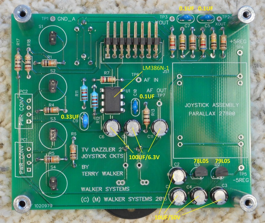
JOYSTICK CONSTRUCTION
Construction of the PC board with all small parts except the switches and
joystick is shown in here.
Note that the capacitors used for U1 and the ones used for the regulators are
physically identical. Be sure to install them in the correct locations and
polarities as shown, otherwise they may explode. The ceramic capacitor values
are difficult to read so they are labeled also. The board will actually work
just fine if all capacitors are the 0.33 UF value, as only the value of C9 is
important. The regulators need to be located as shown in order to work. Unless
you are good at reading resistor color coding, the fastest way to build the PC
board is to simply to install resistors with color bands to match the photograph
in Figure 7. When installing the 16 pin header connector, make sure that it is
not pressed down against the PC board in such a way that the associated plug
would be difficult to install.
The enclosure used here for the joystick box is the Hammond 1590BBCB die cast
aluminum alloy box sold by DigiKey. This enclosure is conveniently already
painted blue, and many colors are available. The paint used on these boxes
is very durable with a high gloss finish. Here is a drawing of the hole
locations needed in the box for the various items. You can download the
hole patterns from the link at the bottom of this page.
If you print two copies of this pattern you can use them for center punching the
hole locations on the top and bottom of the box. Check the outside
boundary dimensions to make sure your printout is properly scaled. When
the holes in the top are drilled, the four 1/4 inch holes for the switches may
need to be oversized to 17/64 inch to fit the push buttons specified since the
switches are actually made to metric dimensions. The 1/8 inch holes in the
top should be countersunk with an 82 degree countersink so that flat head screws
can be used to mount the PC board. The 1 inch holes in the top and bottom
were made by drilling with a 3/8 inch drill and then using a chassis punch to
make the final sized hole. Any method you may have is OK for making the
hole, such as a hole saw or drilling a circle of small holes and filing out to
the desired diameter. If you do the filing method, use a compass to draw a
circle on the pattern with the final 1 inch diameter after center punching and
before doing any cutting. The box is die cast from an aluminum zinc alloy
which cuts and drills easily and fractures if bent.
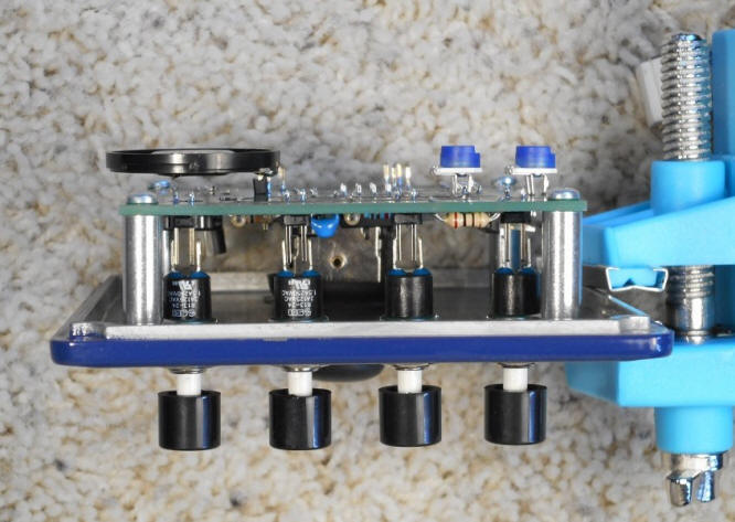
The PC board is mounted to the top of the case since the connections to the push
button switches are rigid and for proper clearance for the joystick handle.
Here is an end view of the box top with the PC board attached, but before the
switch terminals have been soldered. The figure also shows the two trim
pots and speaker installed on the back of the PC board. Standard square single
turn trim pots may also be used.
Mount the switches to the top before attaching the PC board with 3/4 inch long
#4 threaded spacers and soldering the switch terminals. After soldering
the terminals, the switch nuts may be carefully removed and replaced if it is
desired to make changes to the PC board. Note that the black tops of this
type switch pull off, however lateral force on the switch button can easily
break the switch shaft. An alternative switch available is harder to
break, but not as comfortable to use.
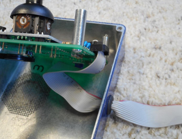
It is convenient to use a 16 conductor ribbon cable with mass terminated plugs
on each end for connecting the joystick unit to the TV Dazzler 2. A 5 foot
long cable was used for the prototype units. The picture below shows how
the cable is folded inside the box to give easy access for installing and
removing the joystick PC assembly.
The ribbon cable was temporarily rolled for pulling it through the rubber
grommet which has a 1/4 inch inside hole and is made for a 3/8 inch hole in the
box. Pull approximately 5 1/2 inches of cable through the grommet.
The cable folds neatly under the PC board when the top is installed. A
small piece of window screen is glued to the inside of the box bottom with RTV
silicon rubber to protect the speaker. Ideally the speaker is mounted near
the screen surface so that the box serves as an acoustic baffle to increase its
efficiency.
Since wire 16 is not used in the cable, it is possible to use mass terminated
male and female DB15 connectors in the cable to make a convenient way of
disconnecting the joysticks from the computer enclosure when not in use.
Just cut off the wire number 16 at the DB15 ends.
Adjustment of the two trim potentiometers can be done by connecting the joystick
assembly to the TV Dazzler 2 J11 connector for power. With the joystick
potentiometer at rest in its center location, adjust each trim pot so that the
voltage at the test points TP2 for Xout (or J11 p7) and TP3 for Yout (or
J11 p9) are in the range of +/-10 millivolts. An alternative method if
the ADC on the TV Dazzler 2 has been carefully zeroed is to read the voltage at
port addresses 19H and 1AH using a monitor program, and adjust the associated
trim pot so the reported value from the input port is 00H most of the time.
Noise may prevent it being zero all the time.
After building the joystick units, they can be tested for proper function with
several programs. One interesting one to use is the program soundF.com,
which uses the joystick X value to control the pitch of a software oscillator,
and the joystick buttons to select the sound. When two joysticks are
installed, each one should have independent control over its own speaker output.
If you use the program sound.com, the pitch is about 10X lower, but then the X
axis controls pitch and the Y axis controls amplitude. Another program to
use is draw.com, which allows either joystick to draw patterns in the TV Dazzler
2 memory space. JS1 will draw patterns using 64 by 64 pixels and 15
colors, while JS2 will draw patterns using 128 by 128 pixels all the same color.
Use the joystick box switches to choose the colors. The sound programs
exit by pressing SW1 and SW4 simultaneously on either box, and draw exits if all
four switches are pressed at the same time on either box.
Users who want better performance than this simple joystick box gives can make
several upgrades to the interface components. The push button switches
have a problem with being easily damaged. An alternative switch which goes
in the same mounting and has a stronger button has the problem of a smaller
button, so it may be hard on the finger of the user after a while. The
joystick chosen in inexpensive and easily available, but has a 'notchy' feel at
the center of motion, and a definite flat spot in the electrical output at the
center of the spans. The speaker is conveniently small but has poor
frequency response and efficiency.
If the joystick PC board is used as an interface device and mounted in a larger
box, then larger and more suitable pushbutton switches could be chosen.
Also, a larger and better quality joystick similar to the original Kraft
joystick could be chosen, but be careful about the question of electrical
resistance variation versus mechanical motion. Finally, the speaker
amplifier can drive any 8 ohm speaker, so a 3 or 4 inch sized speaker could be
used to get better sound volume and quality. These changes will all add
substantially to the quality of the joystick box, but also will increase the
materials cost by 50 to 100 dollars. Board Holes Image (V1.0
10/72016) Cromemco Cable Connections (10/7/2016) Joystick Schematic (V1.0
10/7/2016) JoystickBOM (V1.0
10/8/2016)
Joystick_BOM.pdf (V1.0
10/8/2016)
Other pages describing my S-100 hardware and software. Please
click
here to continue.