It's using the same active termination that appeared on the V3 board. It's probably the same as the V2 board, but I don't want to guess.
The design is a simple OP-AMP providing the bias to drive some TIP transistors to produce a 2.5V reference, then some 270 ohm resistors to each pin.
Cheers,
Josh
From: bbel...@gmail.com
To: n8vem...@googlegroups.com
Subject: RE: [N8VEM-S100:6838] Re: Reorder of S-100 8-slot Backplane PCB
Date: Mon, 27 Apr 2015 17:33:57 -0400
Todd, I have not had the time to open your beta design and look it over, but quick question: is this still using the Compupro active termination that is on the V2 board?
Bob Bell
From: n8vem...@googlegroups.com [mailto:n8vem...@googlegroups.com] On Behalf Of Crusty OMO
Sent: Monday, April 27, 2015 12:20 AM
To: n8vem...@googlegroups.com
Subject: RE: [N8VEM-S100:6830] Re: Reorder of S-100 8-slot Backplane PCB
Hi Todd,
Ok, I've finished rewiring the S-100 9-slot backplane. Please do not build it yet... I want to look it over a few times, since it's all hand routed, there might be problems. I also want to pretty up the Silk Screen.
I've uploaded this beta version for anyone to help look for problems. It's at:
http://n8vem-sbc.pbworks.com/w/browse/#view=ViewFolder¶m=S-100%20backplane
The file is called "S-100 Backplane v4-beta.zip"
Features of the board:
-Includes a custom spaced slot #1 for Front Panel on the IMSAI computer (spacing = 1.04" instead of .75")
-Holes for mounting in either ALTAIR or IMSAI chassis
-There is a "no component" or Trace zone where the board would rest on the rails of an ALTAIR computer.
-Bus traces are all on the bottom, top layer is primarily a fill zone to help shield bus noise.
-2 connectors for power are available, the original 0.2" spaced and a new 0.156" spaced for molex connectors.
-9 Slots in total.
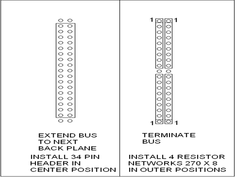
-Board can be extended to another back plane by use of 3 x 34 pin ribbon cables
-The last board can be terminated.
-Reset switch moved to the front
-Grounding jumpers for 3 bus lines (as per previous versions)
Note, Termination uses the same holes that the ribbon cable would, so it's either, extend the bus, or terminate the bus, but not both.
Losses on the board....
-No fuses, I just couldn't squeeze them in... I hope this is ok....
Regards,
Josh Bensadon
From: crus...@hotmail.com
To: n8vem...@googlegroups.com
Subject: RE: [N8VEM-S100:6827] Re: Reorder of S-100 8-slot Backplane PCB
Date: Sun, 26 Apr 2015 15:22:38 -0400
Hi Todd,
I'm well underway on rewiring the back plane. Since it's not a complicated circuit, I am foregoing the schematic and just doing the traces in manual mode. The first slot is spaced 1" from the 2nd slot. Since I want to be able to cascade them, and since the IMSAI board is wider, I moved the Termination to the side and was able to add a 9th slot. The back 8 slots are all 3/4" spaced. When you cascade the boards, the last slot will be 2.25" from the 2nd slot on the next board, ie, skip 2 standard slots and resume 3/4" spacing.
The mounting holes for IMSAI are there, and even when cascaded, they *should* all line up... I hope.
The mounting holes for ALTAIR are just the holes for the S100 connectors, but I was careful to not place components or traces along the width of the two rails. The first slot spaced 1" can be mounted into the existing holes, but new holes will need to be drilled and tapped for the last slot. I haven't removed my ALTAIR Back Plane to look (don't want to upset all the wires, I heard on another post that these wires break easily). But it appears they only drilled and tapped 4 holes on the rails anyway.
I hope to get this board done by tonight... but I recommend you give me another week to look it over for errors.
Cheers,
Josh
Date: Sat, 25 Apr 2015 16:03:29 -0400
Subject: Re: [N8VEM-S100:6825] Re: Reorder of S-100 8-slot Backplane PCB
From: tacom...@gmail.com
To: n8vem...@googlegroups.com
Hi Josh,
Personally I'd prefer your #2, 8.5" with IMSAI and Altair holes.
It looks like fabricating the ALTAIR card guide mounts wouldn't be too bad?
I'm probably not understanding something but couldn't we fix issue with cascading the boards when the first slot is shifted buy ensuring there's enough bare (or with only lower profile parts than the connectors) after the last connector before the edge of the board? Or does that screw up card guides or something on some standard chassis?
Todd
On Sat, Apr 25, 2015 at 1:37 PM, Crusty OMO <crus...@hotmail.com> wrote:
Guys,
Here's our first hurdle.... the ALTAIR back plane is 11" wide. It is like this because the card slot guides are screwed in from the bottom of the board. The IMSAI back plane is only 8.5" wide.
The 8 slot board v2 is 7.25" wide.
It's not a problem to expand to 8.5", but 11" makes it interfere with the IMSAI chassis by about .25"
Option 1. Make it 11", ready for the ALTAIR... IMSAI use will require cutting the board.
Option 2. Make it 8.5", with IMSAI and ALTAIR holes, ALTAIR use will just have to sacrifice the card slot guides.
Option 3. Make it 10.75" with a 8.5" irregular width for the first slot, this will allow it to fit both systems, but only allows a single screw to hold the 5/8" wide card slot guide (otherwise needs 2 screws).
In Option 2, ALTAIR users can always create their own cross beams using 1/2" aluminum angle to support the card slot guides. Here's a picture of the first slot as pictured from the back.
Look closely, you see 2 holes for card slot guides. Now look at the rail that supports this board, it starts near the S-100 connector, this board is supported by the holes of the S-100 connector to two of these rails. New rails can easily be added, see the multiple holes available on the end of the chassis?
The NEXT hurdle involves the fact that the first slot on the IMSAI is spaced just over 1" to slot 2. This is because the first slot is meant to reach the front panel. All the other slots are the regular 0.75" spacing... This shouldn't be too much trouble, but it becomes trouble when wanting to cascade these boards to make larger back planes. There will need to be a sacrifice of one or two slots to maintain correct spacing.
Thoughts?
Regards,
Josh
--
You received this message because you are subscribed to the Google Groups "N8VEM-S100" group.
To unsubscribe from this group and stop receiving emails from it, send an email to n8vem-s100+...@googlegroups.com.
For more options, visit https://groups.google.com/d/optout.
--
You received this message because you are subscribed to the Google Groups "N8VEM-S100" group.
To unsubscribe from this group and stop receiving emails from it, send an email to n8vem-s100+...@googlegroups.com.
For more options, visit https://groups.google.com/d/optout.
--
You received this message because you are subscribed to the Google Groups "N8VEM-S100" group.
To unsubscribe from this group and stop receiving emails from it, send an email to n8vem-s100+...@googlegroups.com.
For more options, visit https://groups.google.com/d/optout.
--
You received this message because you are subscribed to the Google Groups "N8VEM-S100" group.
To unsubscribe from this group and stop receiving emails from it, send an email to n8vem-s100+...@googlegroups.com.
For more options, visit https://groups.google.com/d/optout.
--
You received this message because you are subscribed to the Google Groups "N8VEM-S100" group.
To unsubscribe from this group and stop receiving emails from it, send an email to n8vem-s100+...@googlegroups.com.
For more options, visit https://groups.google.com/d/optout.