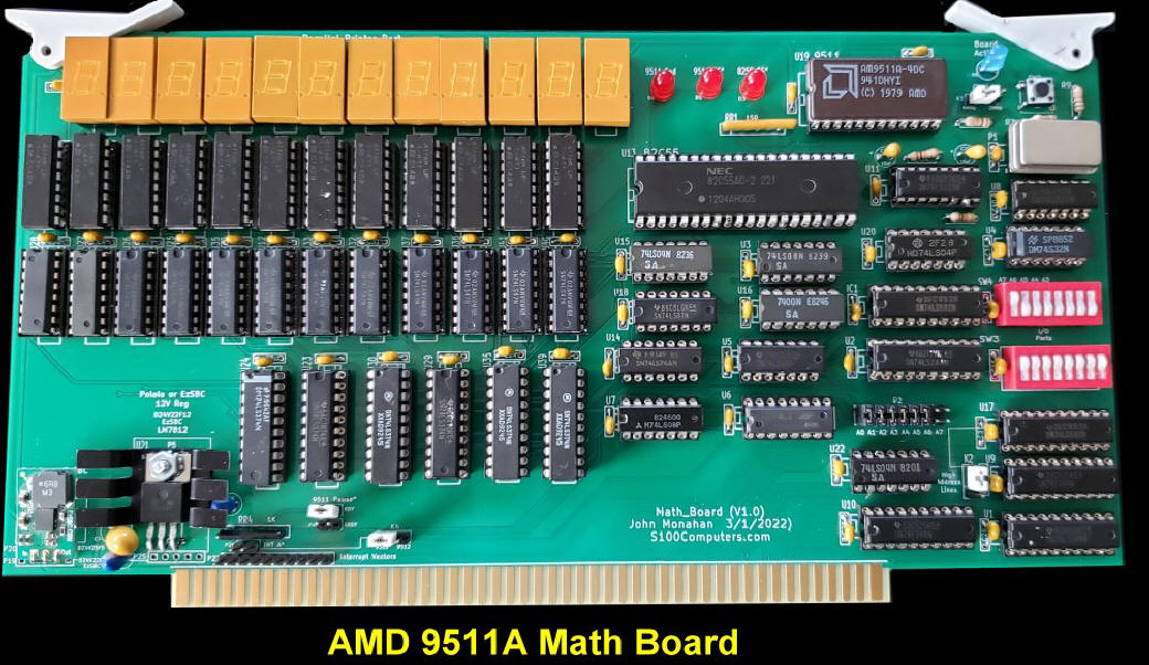
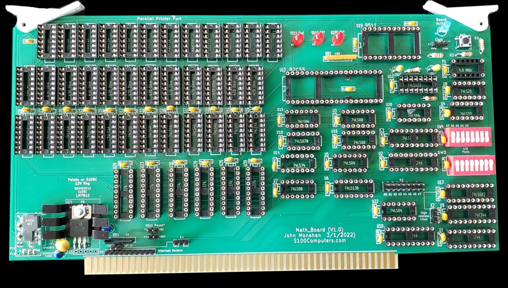
An S-100 AM9511 Math Processor Board.
Introduction
The one thing early 8 and 16 bit CPUs could not do well was doing math
calculations with floating point numbers. While early assembly
language routines were written for assembly and Basic code the calculations
were brutally slow. The solution was to design a special "Math
Processor" chip and off load calculations to the chip. The chip could even
be setup to run independently of the parent CPU interrupting it when done.
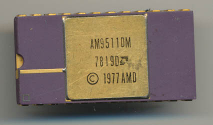
Math processor chips was one thing AMD did well in its early days. Even its
CPU were better in this respect. AMD in 1977 introduced the
AM9511 Arithmetic Processing Unit. It is best described as a
scientific calculator on a chip. It could handle 32 bit
double precision math (via a 16 bit stack/registers) and supported not just
the basic ADD, SUB, MUL and DIV, but SIN, COS, TAN, ASIN, ACOS, ATAN, LOG,
LN, EXP, and PWR. 14 floating point instructions, in hardware, on a single
chip. It ran at up to 3MHz (4MHz in the ‘A’ version) and could interface
with pretty much any microprocessor or microcontroller, providing much
needed processing power. It was designed as a peripheral, so that the main
processor could assign it a task, and then go on about its program while the
AM9511 crunched the math. The AM9511 would then notify the host processor
via an interrupt that it was finished and that the data/status was
ready to be read.
| |
 |
| |
An early AM9511 chip |
The second version, released in 1979 was called the AM9511A. It added
some changes to support synchronous, as well as asynchronous systems. It
also allowed for a slightly higher clock of 4MHz. The design was a success,
so much so that Intel gave up it's own internal efforts and licensed the
design from AMD as the 8231 and the 8231A.
Back in 1979 the IEEE was hard at work at coming up with a standard for
handling floating point numbers, and math functions that dealt with them.
It was important, as every processor should achieve the same results
when performing math. Things such as storage formats, and rounding schemes
had to be standardized. IEEE came up with a standard based on Intel’s 8087
FPU, and the first FPU to be fully compliant was the Intel i387 in 1987.
AMD made the AM9512 to support the draft standard. While similar to the
AM9511, it only supported the 4 basic functions, ADD, SUB, MUL and DIV.
They were however now 64 bit rather than the 32 bits of the 9511. Intel
again licensed the design and produced it as the 8232. However the
8232 did not sell as well as the 9511A/8231A as by now the Intel 8087 Math
Coprocessor was in production. Often back then however designers would
rather use the more versatile, yet not entirely IEEE 754 compliant, 9511.
I am only aware of one S100 Board utilizing the AMD9511A math chip. It was
the CopmuPro
System Support 1 Board. Besides the Math Processor that board also
had RS232 Serial Ports, Interval Timers, 4K RAM/ROM and a Read Time
Clock/Calendar.
Interfacing the chip is easy. It appears as just two I/O ports to a
bus CPU. The lower address is usually assigned to the "Data Port"
and the higher port to the "Command/Status Port".
It is very important to understand that the 9511 is a stack orientated
machine. Data is sent to the data port which ends up going on to the
chips RAM pushdown stack. Each successive pair of bytes pushes
the data down on the stack. Commands are sent to the AM9511 (via the
Command port). It operates on the data sent and places the results on
the top of the stack where they can be read off via the data port.
You can send the data and commands and then leave the AM9511 alone to do the
calculations. When done it will pull its END* pin (24) low. This
can be used as a status bit or an interrupt for the main bus CPU.
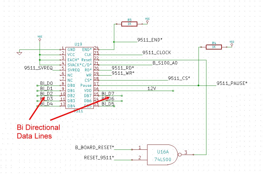
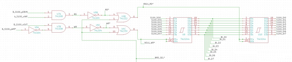
Here is the core circuit:
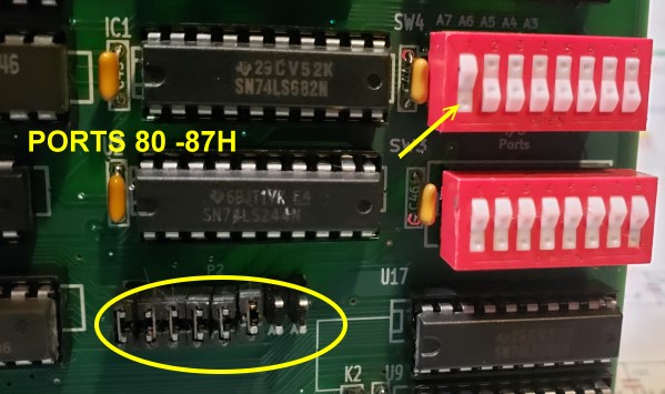
The AM9511A two I/O ports are completely switch selectable on this S100 board
(I use 80H and 81H here), see below.
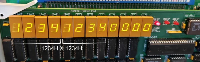
The HEX LED Display.
Since the circuit required on this board is relatively simple I decided to
fill up the board with a row of HEX LED displays. There are 6 pairs
of them across the top of the board. Each pair is meant to represent
the AM9511A push down stack of bytes send to the data port of the chip.
As a new byte is added the HEX display is shifted to the right by one digit. These LEDs are meant to display the current status of
data at the very
top of the ASM9511 RAM stack.
Please note however the display is not reading directly from the chip it is
simulated in the boards support software and is mainly used for software
debugging/development.
In a real time library/application the display can be ignored if you wish to
attain high speed calculations.
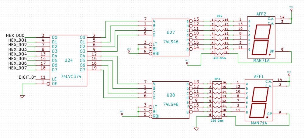
The most elegant solution for a HEX LED display would be to use expensive TIL 311A's.
They take a 8 bit input, latch it and display the HEX character directly.
However these day they have become rare and expensive. I cheaper
approach is to use common LED displays and use a 74LS46 to convert 4 bits
into a HEX display. Unfortunately the data also must be latched with a
74LS374 leading to 3 DIP chips per digit.
Here is a picture of a single digit circuit:-
and here is a picture of an active display:-
Building Board - Step by Step Instructions.
First inspect the board for scratches or cut traces.
Insert all IC sockets, Caps, resistors, the clock generator (2 MHz or 3 MHz), resistor networks, the voltage regulator and jumper pins.
I like to solder clock clock generators directly to the board. If you do use a
socket be sure the thin wires make good contact and/or use the special
sockets for these "chips".
Also make sure to position pin 1 correctly. Take care to get the polarity of
caps correct.
The square pad is the positive side. Also note that the resistor
network RR4 has pin 1 on the right hand side.
Note there are two sockets for the Pololu 5V regulator.
While the D24V25F5
is still available
(and uses P20), it seems Pololu is suggesting users use the newer
D24V22F5's
(5V, 2.5 Amp) units, it has a different pinout, use this one in P19
(not P20). The AM9511A also requires a 12V supply. You can use
either a
Pololu 12V regulator (D24V22F12)
or an old LM7812 regulator. While the AM7812A runs quite hot and draws
about 70 mA I have found a heat sink is nor really requires for the LM7812.
Be sure you get these regulators correct. To be safe once inserted, check
the voltage in your system on a 5V and 12V IC pin, (see the schematic) with
no other chips yet inserted on the board.
BTW, You can also use the
EzSBC 5V and
EzSBC 12 V regulators. These are in fact a little cheaper.
Both these regulator 3 pins go into the 3 right-most pins of P19 and P25.
When adding the LED's be sure to orient them correctly. (Usually the longer
lead in the square pad).
Here is a picture of the board before adding IC's.
We will assume only 8 bit IO port addressing initially so jumper K2 2-3.
We will use ports 80H-87H in the software below. If you have a
conflict with other boards use a different IO port block and adjust the
software equate in MATH.Z80.
Install all the non HEX display ICs except the actual AM9511 but including
the 82C55A (U13). Be sure jumpers P3, P4 and K4 are
not installed.
First we will check the chip select circuit for the 82C55A and AM9511A
is working correctly.
Adjust the dip switches SW3 and SW4 as shown here. (This selects ports
80H to 87H).
With your Z80 monitor write in RAM at 0H
DB 80
C3 00 00
Pin 18 of the AM9511 (U19) socket must pulse low continuously.
Repeat for port 81H
Next enter at 0H in RAM
DB 82
C3 00 00
and jump to 0H in RAM.
Pin 6 of the 82C55A (U13) must pulse low continuously.
Repeat for port 83H,84H,85H.
There must be no pulse for any other port value
The 82C55A is a very flexible parallel ports IO chip. It has three 8 bity
ports who's direction can be changed/altered in software. It is always
configured by writing to port D (85H here).
Please see here for
more information about programming the chip.
We will configure the 82C55A with ports A and B as 8 bit output ports and
port c as an 8 bit input port.
This is done by sending 81H to its port D (85H).
Then output to port 82H a value of
00H. Pin 4, 3, 2, 1, 40, 39, 38
and 39 of U13 all should be low.
If desired check port 83H and input port
84H.
At this point you probably have a functioning circuit. Insert the AA9511A
chip and load the program MATH.COM into RAM at
100H.
You can interface the 9511 directly from your
Z80 Master monitor...
Assuming the boards base address is 80H with
the following keyboard entries we will add 1234H
to 5678H:
QO
85,81
;Set 8255A to Ports A & B output, Port
C input
QO 82,00
;Set 8911 C/D* pin to low (Data)
QO 80,34
;Send first low byte
QO 80,12
;Send first high byte
QO 80,78
;Send second low byte
QO 80,56
;Second second high byte
QO 82,80
;Set 9511 C/D* pin to high (Command)
QO 81,6C
;Send the ADD command
QI 82,00
;Set 8911 C/D* pin to low (Data)
QI 80,01101000 ;Get high byte
data (68H)
QI 80,10101100 ;Get low byte data
(ACH)
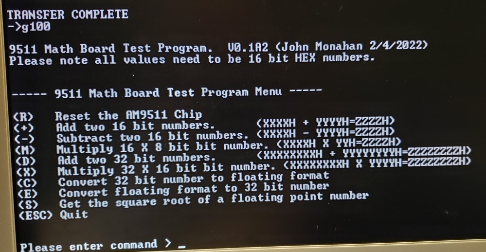
I have written a short Z80 program to demo the boards capabilities called
MATH.COM. It can be downloaded from the bottom of this page.
Using your Z80 Master monitor "X" command load it to 100H in RAM and jump
there. (There are equates in the code to also run it under CPM).
It should signon like this:-
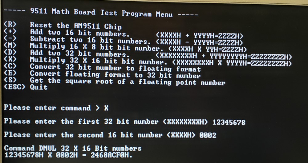
The commands should be fairly straightforward. For example to multiply
a 32 bit number by a 16 bit number:-
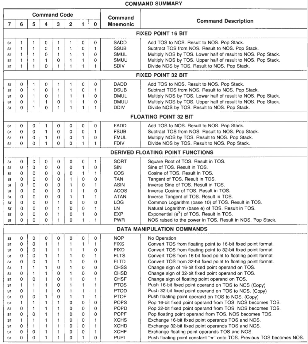
The main power of the AM9511 however is its ability to work with floating
point numbers. Here is a table of the 9511's commands.
As you can see all are single 8 bit commands that act on the word(s) on the
pushdown stack.
If we push 1234H on to the stack and then
0002H on to the stack and then we send the
SADD (6CH)
command. The top two bytes on the stack will be
1236H.
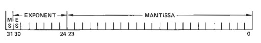
Floating point numbers are always entered as 32 bit words with a 24 bit
mantissa and a 7 bit exponent.
Please see the datasheet
for a complete description of how the AM9511 represents numbers.
Using floating point numbers in assembly language is quite complex -- and
above my capabilities.
See the bottom of this page for more information.
More often you will use a high level language to work with them. The
common languages supply libraries.
While the ports are movable on this board you will probably have to tweak
the 9511 port IO to splice in the board hardware.
The core routines to send data, a command and read data back from the 9511
are as follows:-
DATA_9511_OUT:
;Note bit 7 of the 8255A port A is normally 0 (Data Port selection)
PUSH AF
LD A,0
OUT (CHIP_8255_A),A
;Select 9511 Data port
POP AF
OUT (MATH_DATA_PORT),A
;So the lower (data) port of the 9511 is selected
DATA_OUT:
IN A,(CHIP_8255_C)
;Wait until the pause goes back high
BIT 1,A
JR Z,DATA_OUT
RET
DATA_9511_IN:
LD A,0
OUT (CHIP_8255_A),A
;Select 9511 Data port
IN A,(MATH_DATA_PORT)
RET
CTRL_9511_OUT:
PUSH AF
LD A,10000000B
OUT (CHIP_8255_A),A
;Select 9511 Command port
NOP
NOP
NOP
POP AF
OUT (MATH_CTRL_PORT),A
;Send command
LD A,0
OUT (CHIP_8255_A),A
;Set back to the default data port
DATA_OUT1:
IN A,(CHIP_8255_C)
;Wait until the pause goes back high from 9511
BIT 1,A
JR Z,DATA_OUT1
RET
The LED HEX Display.
It is important to understand what the 12
digit HEX display is showing. It is always the current bytes on the
top of the 9511A Data pushdown stack. As each byte is entered to
the 9511A data port the stack digits are pushed one digit to the RIGHT.
Most instructions involve less than 12 digits but if you are calculating
with a large numbers digits they may be shifted over the RHS "edge" .
They are still the on the 9511 stack it's just the is no room to display
them. When a calculation is made the results are also put on the
stack. However they are not displayed on the HEX display because they
are read (and thus popped from the stack) by the 9511A.
Note, you can have multiple back to back commands acting on whatever is
on the stack. You can double push data etc.
For hardware experts, you will note I use parallel ports A & B on an 8555A to
update the HEX display. However I also use bit 7 of its Port A to
set the 9511A data or control port address. I found that with a 10
10MHz Z80 CPU you cannot use the address line A0 (High/low) for its
Code/Data pin. It appears the line has to be settled before a
read or write is carried out. If you don't do this and instead
simply use address line 0 you will get an "echo" of the commands by sent to
the 9511A control port on its data port as well. Normally
not a big deal -- you just read the byte, ignore it and then read the actual
calculation bytes on the data port. However this screws up
multiple byte commands such as
SMUL
and
SMUU.
The good news in the AMD 9511A-4DC works fine with a 4mHz clock.
The jumper K1 determines if the 9511 clock is 2MHz or 4MHz.
BUGS
There is a slight error in the circuit for this board that leads to the
"Board Select" LED being on all the time - even when the board is not being
accessed.
Unfortunately the two inputs to U16A (a 74LS00) should have been a 74LS08
chip. While not exactly "Board Select", a simple patch is
to bend out pin 2 of U16 and bridge its pin 1 to pin 2 on the back of the
board.
A Production S-100 Board
Realizing that a number of people might want to utilize a
board like this together with a group of
people on the
Google
Groups S100Computers Forum, a "group purchases" was formed. It is now closed.
Please see here
for more information. Please do not contact me directly.
Please note all the above
clearly applies only to people who know what they are doing and can do
a little soldering and board assembly. There will be little hand holding
at this stage.
The links below will contain the most recent schematic of this board.
Note, it may change over time and some IC part or pin numbers may not correlate
exactly with the text in the article above.
Introduction to Floating Point Numbers
(V1.0 3/2/2022)
SIMPLE AM9511 MATH Demo Program (Text)
(V1.0 3/2/2022)
SIMPLE AM9511 MATH Demo Program (.Zip File)
(V1.0 3/2/2022)
MOST
CURRENT MATH BOARD SCHEMATIC
(V1.0 3/2/2022)
MOST
CURRENT MATH BOARD LAYOUT
(V1.0 3/2/2022)
MOST
CURRENT MATH BOARD BOM (.pdf)
(V1.0 6/28/2022) Supplied
by Rick Bromagen
MOST
CURRENT MATH BOARD BOM (.xls)
(V1.0 6/28/2022)
Supplied by Rick Bromagen
Most current
KiCAD files for this Math board
(V1.0 3/2/2022)
Most current
Gerber files for this Math board
(V1.0 3/2/2022)
Other pages describing my S-100
hardware and software.
Please click
here
to continue...
This page was last modified
on 07/03/2022