S100 Computers

HomeS-100 Boards HistoryNew BoardsSoftwareBoards For Sale
ForumOther Web Sites NewsIndex  

The Intel Edison II S100 Bus CPU Board.


Edison II CPU Board
This board is a major extension of the first Edison CPU board. To understand much of what is written below it is essential you read about that board first.  This write-up is written with the understand you have done so and are quite familiar with both the hardware and software for that board.

Essentially the Edison II board is two boards in one.  The original Edison board was "one way";  Once it was given control from the bus master it ran the bus much like any of our other slave CPU boards, and while, as we saw the onboard Monitor code was written in C because of the speed of the 64 bit dual CPU's on Edison module board they had no difficulty providing fast signal service to the S100 bus.

This board essentially fills in the patch area with extra 74LSxxx chips such that the board is now "bidirectional".  Not only can it control the bus, it now can be controlled by the bus when another CPU is a master.    In particular it can function as a self contained bus signal monitor.  There is even an onboard USB port to send the info to an external terminal.  That's the good news.  The bad news is now the board has become quite complex.   There are many moving parts so to speak.  It will require a very careful step by step build to get it fully functional.  If you already have the original Edison board working life will be very much simpler.   You can in fact you can transplant almost all the "V1" boards components to this board and just add the extra 74LSxxx chips.  However as we will see below,  while the code/pinout of the CPLD (U6) is very similar it will have to be reprogrammed.


The Hardware
The interface of the Edison with the S100 bus is via an Atmel 1580 CPLD exactly like we did for the V1 board.  As I said for that board, all the input/output pins of the Edison are 1.8 Volts max.  In fact if you input a voltage greater than that you will burn out that gate/buffer on the Edison.  One has to take great care that the Edison breakout board never sees a voltage greater than 1.8 volts. The unit in most unforgiving in this respect. Since the S100 bus drivers and the CPLD require 5 volts we use a "level shifter" to bridge the two voltage levels.  We use the common Ti TXB0108 8-bit Bidirectional Voltage-Level Translator to bridge the interface.    Unfortunately these chips these days only come in a SMD format.  While not difficult to solder, there are pads on the board to do so, for convenience for most users, we will use these chips in a 20 pin "adaptor" DIP format.  Again these are common, for example on here.
   
As in the case of the V1 board there are not enough general purpose input/output lines on the Edison Breakout board to directly interface the S100 bus IEEE-696 24 Address lines. We set or read the S100  address with TBX0108-A (8 bits) by latching three 8 bit bytes outputs into three 74LS373's with TBX0108-B (U23) or reading them via TBX0108-C (U18).  Because the Edison is so fast and only one 74LS373 buffer is involved there is little bus delay.  See the following diagram:-
  
  Edison II Diagram
   
Data (8 bit), from the S100 bus lines travels to the Edison via the level shifter TBX0108-C (U18). All S100 bus data in monitoring arrives also via this buffer. This includes address lines, S100 bus data in/out lines, status and control lines.  The real heart of the board is TB0108-D and E.  These chips transfers the main Edison bus control signals to the CPLD.  Within the CPLD the S100 bus status and control signals are synthesized as is the case for the V1 board.  However now the CPLD takes on another role.  It is involved in latching and reading of the S100 bus monitoring using the 74LS373s (U32, U33, U34, U22, U35, U7 and U31).  It has now become a bit more complex over the one way code of the V1 board. Here is the core WinCUPL code within the 1508 CPLD.

/* Synthesize the S100 Bus Control and Status signals */
/* ====== ADDRESS BUFFERS CONTROL ================== */

LATCH_ADD1 = ((!ADDRESS1 & !XFERII & !TO_BUS)                  /* Latch U8 data on high (and U32 + U33 +U34 if TO_BUS is high) */
           # (!ADDRESS1 & XFERII & TO_BUS));

!DIAG_LED1 = LATCH_ADD1;

LATCH_ADD2 = !ADDRESS2 & !XFERII & !TO_BUS;                    /* Latch U9 data on high */
LATCH_ADD3 = !ADDRESS3 & !XFERII & !TO_BUS;                    /* Latch U2 data on high */

!BUS_ADD1_READ = !ADDRESS2 & ADDRESS3 & !RW_PULSE & TO_BUS;    /* For bus monitoring OE* lowest 8 bit address on U32 */
!BUS_ADD2_READ = ADDRESS2 & !ADDRESS3 & !RW_PULSE & TO_BUS;    /* For bus monitoring OE* middle 8 bit address on U33 */
!BUS_ADD3_READ = !ADDRESS2 & !ADDRESS3 & !RW_PULSE & TO_BUS;   /* For bus monitoring OE* highest 8 bit address on U34 */

/* ====== S100 BUS DATA FROM EDISON (U4) =========== */

!S100_DATA_OUT = !DATA_WR & !XFERII;                           /* Data OUT via U4 OE = LOW */

IO_RAM_WR = (!E_MEMW # !E_sOUT # !E_sINTA) & !S100_DATA_OUT;   /* Raise pin 11 of U4 to LATCH DATA. Note, active HIGH */

/* ====== S100 BUS DATA TO EDISON (U5) ============== */

!S100_DATA_IN = !DATA_RD & !XFERII & !TO_BUS;                  /* Data IN via U5 OE = LOW */

IO_RAM_RD = (((!E_MEMR # !E_sINP) & !S100_DATA_IN & !TO_BUS)   /* Raise pin 11 of U5 to LATCH DATA. Note, active HIGH */
         #  (!E_MEMR & !RW_PULSE & XFERII & TO_BUS));          /* OR, when in monitoring mode to latch data for U22 & U35 */


/* ============ STATUS LINES ========== */

bpSYNC   = !E_pSYNC & !XFERII;
!bpSTVAL =  bpSYNC & !XFERII;                                  /* Pulse S100 bpSTVAL line, LOW */

!bsOUT = !E_sOUT & !XFERII;                                    /* sOUT status signal to S100 bus, HIGH, inverted by U16 */

!bsINP = !E_sINP & !XFERII;                                    /* sINP status signal to S100 bus, LOW here , but inverted by U16 */

!bMEM_WR = !E_MEMW & !XFERII;                                  /* MWRT status signal to S100 bus, LOW here , but inverted by U16 */

!bMEM_RD = !E_MEMR & !XFERII;                                  /* sMEMR status signal to S100 bus, LOW here , but inverted by U16 */

!HALT = !E_STOP_REQUEST & !XFERII;                            /* S100 "HALT" line (is 8080 Specific, not really used on S100 bus */

!bsM1 = bpSYNC # !bINTA ;                                      /* CPU code read for S100 bus. Not really used on S100 bus */

bsWO = IO_RAM_WR & !XFERII;                                    /* I/O Write */


/* ============ CONTROL LINES ========== */

bpDBIN = !DATA_RD & !RW_PULSE & !XFERII;                        /* Command to pulse S100 bpDBIN line, HIGH */

!bpWR = !DATA_WR & !RW_PULSE & !XFERII;                         /* Command to pulse S100 bus bpWR* line, LOW */

!bINTA = !E_sINTA & !RW_PULSE & !XFERII;                        /* Pulse S100 bus sINTA line (High on S100 bus via U16) */

!SLAVE_RESET = !E_WAIT & BOARD_ACTIVE & !TO_BUS;                /* Return control back to S100 master (Z80) IF Edison controls bus*/

!E_S100_INT = S100_INT & !XFERII;                               /* Interrupt from S100 bus */

!S100_XRDY = !E_WAIT & BOARD_ACTIVE & TO_BUS;                  /* Add wait states to S100 bus if in monitoring mode */


/* ======
S100 BUS DATA TO EDISON (Monitoring mode >> ONLY <<) ===== */
/* Note these signals will NEVER see the S100 bus because XFERII &
TO_BUS are high */
/* Remember also they are counting on IO_RAM_RD from above pulsing high */

!BUS_STATUS_READ = !E_sOUT & !E_WAIT & XFERII & !RW_PULSE &
TO_BUS;     /* For monitoring Mode use E_sOUT signal for OE* for U7 */
!BUS_CTRL_READ = !E_sINP & !E_WAIT & XFERII & !RW_PULSE &
TO_BUS;       /* For monitoring Mode use E_sINP signal for OE* for U31 */
!BUS_DI_READ = !E_sINTA & !E_WAIT & XFERII & !RW_PULSE &
TO_BUS;        /* For monitoring Mode use E_sINTA signal for OE* for U22 */
!BUS_DO_READ = !E_pSYNC & !E_WAIT & XFERII & !RW_PULSE &
TO_BUS;        /* For monitoring Mode use E_pSYNC signal for OE* for U35 */

/* ====== LEDs etc. ========== */

!DATA_OUT_LED = !S100_DATA_OUT;                                  /* Flash Data Direction LEDs */
!DATA_IN_LED = !S100_DATA_IN;

E_STOP_REQUEST = !STOP_SWITCH & (!bsOUT # !bsINP # !bMEM_WR #!bMEM_RD # !bINTA) & !EDISON_READY; /* HIGH with Switch SW1 grounded */

As you can see even though we had 32 Edison GPIO pins to play with we still did not have enough pins to control and monitor the S100 bus.  Fortunately we can multiplex some pins since certain combinations will never occur in the bus controlling state.  Again you can see all of the above 1508 CPLD internal code is in fact quite simple.  The 1508 is really only there because the Edison does not really have enough GPIO pins to directly control the S100 bus. In fact you could probably get away with four or five GALs instead of the one CPLD. 

Note the Edison does supplies a 1.8V outlet (JP19 pin 2).  This is used to drive the level shifters on the TBX Adaptor board.  Since the is no patch area on this board there is therefore no need for the onboard 1.8V (LD1117V18) regulator we had in the V1 board.

Finally you will see the board utilizes our old "GAL0"  GAL (U14).  We have used this design on all our S100 bus slave boards.  Inputting from Port ED from the Z80 monitor will activate the Edison (When LED D4, Edison ready, is on).  If you use our V3 SMB board you don't actually need this GAL, Just lower one of the four TMA lines as described for that board.

Step By Step Building the Edison Board
The build instructions are still fairly simple for this board but because it is a complex board building it should not be rushed.  As always, first examine the bare board carefully for scratches or damaged traces, use a magnifying glass if need be.  A broken trace is almost impossible to detect by eye on a completed board.  Here is a picture of the bare V2.4 board:-
  
  EdisonII Bear Board
  
Please note the build pictures for the board below are with the prototype V2.3 board.  The board you have is identical except that U40 (a 74LS2440) driver was added to insure all TXB0108 level shifters never see more than one TTL load. (See below).

Build the board up in functional steps. Avoid the temptation of adding everything at once and popping it into your S-100 box. Step by step is faster in the end -- trust me.  We will set the board up as a true S100 bus slave.  By programming the CPLD and with the additional circuitry on the board it can in fact run as a bus master.  I will leave this arrangement to our more experienced users  (hint, pins 44, 80, 36 and 37 of the CPLD).
        
Solder in all the required IC sockets, resistors, resistor arrays, capacitors, jumpers, and the 5V regulator.  Do not add the LED's yet. Be sure you put the resistor arrays in with the correct orientation of pin 1. Check their values before soldering (they are difficult to remove).  Insert all jumper arrays. Be sure and have pin 1 of the CPLD socket on the LHS.
  
For prototype boards I generally use "double swipe" IC sockets. For a critical board like this I prefer to use "Machine Tooled" IC sockets.  However they are more expensive and you have to be particularly careful not to bend the IC pins.  The two clock oscillators can have their own special sockets (e.g. Jameco #133006) but actually I find the "Machine Tooled" IC sockets make a better connection.  I in fact solder the 2MHz oscillator (P7) directly to the board since it will never be changed.  Likewise I solder the USB converter (P13) directly to the board.   For testing,  you can get away with just pressing the chip directly into the board holes without soldering it in.
 
Place the board in the bus. Check the voltage to sockets on the board is about 5V by placing the board in your S-100 system using an extender board. With no load you will typically get 5.00V  (+/- 0.2V).  BTW, your system should boot and run correctly with its Z80 master CPU board. If not, you have a serious solder bridge somewhere on the board.  Before you do anything else with a magnifying glass go over every socket on the board and examine for proper solder joints. I like to "reheat" each joint just to be on the safe side. The silk screen/varnish on these boards us quite thick. It's easy not to have a good solder joint for the ground pins.  Double check.   Extra time here will save you hours later, (Been there, done that! ). 

Here is a picture of the board at this stage.
       
  Stage 1
   
You may wish to solder the Edison motherboard directly to the S100 board (see below) , if so do not insert the female connectors for the Edison on the LHS.

Next insert all 5 LED's. Before soldering them in place ground one at a time pins 3,5,7,9 & 11 of U13 to be sure they are OK.    (I always use a blue LED for D7 "Board Active"  in my systems). 

As for the V1 board, there is one major construction decision you need to make with this board right at the start.   The Edison + adaptor unit sits quite high on the board.  If you use 0.1" sockets to house it,  the unit will prevent the next S100 bus slot from being used.  If you solder the Edison+Adaptor directly to the board this is not a problem.   The only issue with the latter is that the breakout board is a little expensive and very difficult to remove if you damage it. Fortunately the more expensive Edison "chip" itself is easy to remove from the breakout board itself, but if anything is going to be "blown" it will probably be on the breakout board.   You will also need to clip the J1 and J2 jumper pins.  J2 is unused here. J1 should be shorted.  The 8V power to the board (J21) also needs to be bent at right angles.   Here is a picture of the mini-breakout board.
  
  Mini Breakout board

The TXB0108's also sit quite high on the board if you use the Jameco #2172560 sockets it's a tight fit in most motherboards.  I found 22 pin "SIP Sockets" at Anchor Electronics that are ideal. They are low profile but you have to cut them to 10 pins. You could likewise cut 40 pin regular IC sockets.  The aim is to not have the level converters too high on the board to prevent the board sitting next to another board in the bus.  Of course you can always solder the TXB's directly to the board or solder the surface mount chips directly.  Please see the bottom of this page first however.
  
  Sockets
   
Having decided on the above, next you need to insert the 1508 CPLD (U6) and program it.  If you are using a new CPLD you could do it later, but if you are reprogramming an old one depending on the code there may be direction/pin conflicts.  Program the CPLD with the code supplied at the bottom of this page.    Note also the code in the V2 CPLD is different from the code in the V1 board.

Remove the CPLD after programming it.
          
Next you need to program the GAL (U14) again with the code at the bottom of this page.  You can also use the GAL0 from the V1 board.
Add the P12 (16MHz Oscillator) and P7 (2MH Oscillator).  Add U17 & U21. Jumper P8 1-2, K1 2-3. 
With the Z80 "O'" command active the S100 bus TMA0 line.  P8 1-2 should go from High to Low and back to High after each "O" command.
Add U3, U24, U13, U19 and U39. Insert the Edison Unit. Hook up the +8V power supply to it.  Add back the already programmed CPLD.
Jumper K4 2-3, and P18 1-2. Jumper P9, P28 1-2. Add the Edison board.
Please remember that for 3 or more pin jumpers, pin 1 is always the square pad. It is not necessarily the one on the top, or LHS.

Power up the system.

As described for the Edison Board ,  launch the Intel Eclipse IDE. Connect to your Edison unit over to a WiFi connection (as described for the V1 board).
Edit the S100_EdisonII.c code so TEST1 = TRUE. Compile and run.
This will activate the following test code within the program (after initializing everything):-

while(TEST1)                                                  // <--- DIGNOSTIC TEST (Loops forever if active)
    {
    mraa_gpio_write(pin[EDISON_READY],LOW);                   // LOW from Edison board -> LED D4
    sleep(1);
    mraa_gpio_write(pin[EDISON_READY],HIGH);                  // HIGH from Edison board -> LED D4
    sleep(1);
    printf("S100_Edison running. LED D4 should Flash On/Off\n");
    }


The "Edison Ready" LED D4 should flash On/Off light up. 
When it is on,  use the  Z80 "O" command  and show that the "Edison Active" D7 LED now also flashes on/off.  Here is a picture of the board at this stage.
    
  Stage2
   
Note the two surface LED's on the Edison board also should light up. Do not go further until you get the above test to work.  If need be,  modify your CPLD code to light up the "Diagnostic LED" (D5)  to step through the initialization code. If you cannot get the D7 LED to light up,  modify the following lines in the CPLD code by temporally removing
!EDISON_READY from each line.   You must get ACTIVATE_EDISON (D7 LED), to go low before you go further.

!XFERI = reg0 & pHLDA & MASTER_RESET
& !EDISON_READY;                    /* Only activate when Edison is ready */

reg1.d = reg0;
reg1.ck = pHLDA;
reg1.ar = !reg0;
!XFERII = reg1;

BOARD_ACTIVE = reg1 & MASTER_RESET
& !EDISON_READY;                      /* Active HIGH */
                                                                         /* Note this will also light up the Edison Active LED */
reg2.d = reg1;
reg2.ckmux = !LOCAL_PHI;
reg2.ar = !reg1;

!ACTIVATE_EDISON = reg2 & MASTER_RESET & BOARD_ACTIVE
& !EDISON_READY;    /* LOWER the Activate Edison line (U12, pin 19) */

You are now using the Edison Eclipse IDE to pass back and forth handshake signals between the CPLD and Edison. This test is the very heart of the board. It must work for everything below to work.  BTW, you actually don't need the U14 GAL if you switch CPUs via our V3 SMB.

Next add U8, U9, U10, U2, U15, U25 and U16. Jumper JP5 & JP4.

Edit the S100_EdisonII.c code so only
TEST2 = TRUE. Compile and run.
If you have the SMB you should see the address lines in your system increase from 0 to FFFFFH over time.
Here is the relevant code within S100_EdisonII.c.

while(TEST2)                                  // <--- DIGNOSTIC TEST (Loops forever if active)
    {
    printf("The S100 bus address lines should increase from 0H to FFFFFH\n");
    for(i=0;i < 0xFFFFF;i++)
        {
        SetRAMAddress((long)i);               // Set the S100 bus address lines
        Send_sMEMR();                         // Send pSync and raise sMEMR status line on S100 bus (will stay up).
        Send_pDBIN();                         // Send pDBIN pulse to S100 bus
        EndBusCycle();                        // Also Clear the S100 Bus Status Line
//      printf("Address = %x\n",i);           // Display current address within the Eclipse console
        usleep(10000);
        }
    }

 Here is a picture of the board at this stage:-
       
  Stage 3
          
Next add U5 and U4 and U36.
Edit the S100_EdisonII.c code so only
TEST3 = TRUE. Compile and run.
You should see a continuous stream of the number "3" on you console.  Here is the relevant code:-

while(TEST3)                                    // <--- DIGNOSTIC TEST (Loops forever if active)
    {
    printf("The S100 bus console should continuously display '3'\n");
    while(TRUE)
        {
        WritePort(CON_OUT_PORT, 0x33);          // Write a 3's to CON_OUT_PORT continuously
        usleep(1000);
        }
    }

Edit the S100_EdisonII.c code so only TEST4 = TRUE. Compile and run.
Any keyboard character you type should appear on your console. Here is the relevant code:-

while(TEST4) // <--- DIGNOSTIC TEST (Loops forever if active)
    {
    char c;
    printf("Read a keyboard character and print it on screen\n");
    while(TRUE)
        {
        while(!GetStatus());                      // Check if a character is available, wait if not
        c = ReadPort(CON_IN_PORT);                // If so get the character
        WritePort(CON_OUT_PORT, c);               // Write a 3's to CON_OUT_PORT
        }
    }

Here is a picture of the board at this stage:-
  
  Stage 4
   
Do not go further until you get these routines to work. 
Once you have these working you are well on your way to having a completely functional system.


If the above is OK, add IC1 to the board.   Jumper JP6 and JP23.
Within Eclipse/S100_Edison set
TEST1,2,3 & 4 to FALSE. Compile and Run. 
With the Z80 "O" command now the complete Edison monitor with its menu should sign on.
Here is a picture of the board at this stage:-
  
  Stage5 
  
Here is what you should see on the S100 Console:-
   
  Menu1
    
At this point the board functions essentially like the V1 Edison board.  Remember however that the Edison and CPLD pinouts are slightly different and require the V2 versions of the software provided at the bottom of this page.  Before you go further thoroughly checkout the menu commands before continuing to the next step.  A problem at this stage will only "fester" and get worse as you go further.

Next we will get the USB/Serial port on the board working.   We will use our tried and true USB adaptor,  the DLP USB245R Adaptor. We used this adaptor previously with our Serial I/O board and ZSBC board. Communication at a fundamental level over a USB cable is extremely complex both in terms of software and hardware. To facilitate these connections a number of companies have made drop in chips that look on the computer side of things as a simple serial or parallel port. The chip transparently handles the very complex handshaking of the USB communication process -- in this case to a receiving USB port and Windows driver on my PC.  The unit we use is the parallel port version of the DLP Designs USP adaptor (DLP-USB245R).  I obtained it from Mouser, but I'm sure its available elsewhere. It costs about $24.  For a complete description of the chip see here (The spec sheet calls it a DLP-USB1232H. The DLP-USB245R behaves the same).

The interaction with the chip is very easy. It has an 8 bit parallel input/output port which can be tri-stated.
 
USB Port Chip   DLP Chip

When pin 12 (WR) goes from low to high the DLP chip reads in the 8 bits of data and sends it out on the USB cable.  When pin 11 (RD*) goes low, each 8 bit of data in a FIFO buffer that arrived over the USB cable is put on the 8 bit data bus (one byte per pulse).  There are two status pins, TXE (pin 14), when high do not write to the chip (is it's busy). RXF (pin15), when high at least one byte of data is available.  I/O with this chip could not be simpler, particularly in C code! 

The pins on the USB1232H  "chip" are quite thick.  I used a 18 pin DIP "double swipe" socket to seat the chip.  Be sure beforehand the socket will accommodate the pins. Some Auget sockets will not.   Also the pins are too long, causing the chip to be too high/close to the next S-100 board on the bus. Trim them to half their length. If you wish to not have the DLP chip stick up too high you can solder it directly to the board.  The holes on the board are narrow enough for a temporary tight fit for testing before you solder it in permeably.

Before adding the chips below, check that pin 1 of U37 and U38 never goes low in the above signon.
Insert U37, U38 and the above DLP USB unit in P13.  Note pin 1 is at the bottom RHS.
Hookup a USB serial connection to your PC and launch a TTY terminal interface.   The above DLP chip does not seem to care what Baud rate etc. you use.  (I use 19200, 1 stop bit,  no parity).
 
Edit the S100_EdisonII.c code so only
TEST5 = TRUE. Compile and run.
Any keyboard character you type (on the TTY terminal, not he S100 keyboard), should appear on TTY terminal on your PC. Here is the relevant code:-

while(TEST5)                 // <--- USB PORT DIGNOSTIC TEST (Loops forever if active)
{
     char c;
     c = USBGetChar();
     USBPutChar(c);
}

We will use this interface when the Edison board is analyzing the S100 bus signals to convey information. 
Using the Edison II menu "X" command, (see below)  we can set the "
TO_BUS" global variable in the EdisonII.c code to LOW. This will cause the "To Bus LED", D3 will go out and the "From Bus LED", D6 will light up.

Add U7, U33, U35, U31, U32 and U34. All sockets should have an IC at this point. 
There are two options to add the run "Stop Switch" (see below), you can add a micro-pushbutton switch at "SPST" or a small switch (or jumper) at SW1. Only one is needed.

Next we will utilize software to switch the Edison to/from the mode where it can monitor the major S100 bus signals while running a different CPU.

The Edison Software
Total control of the S100 bus is obtained by programming the Edison in C code.  The C code is actually quite large with many repeatedly utilized routines.  These routines totally synthesize ALL the S100 bus signals.  As far as any other S100 bus board knows, there is just another temporary master running the S100 bus -- just like for example, our  6502, 8086 or 68K  CPU's.  You can display RAM, query a port, output to a printer or speech synthesizer  etc.  It's very important to appreciate that we have two Atom Silvermont cores running at 500 MHz and one Intel Quark core at 100 MHz driving the bus.  This is like placing a Lamborghini engine in a Honda Civic.  Even though our Edison C code appears verbose,  the chip still spends most of its time waiting for the S100 bus to respond.  Simple (no-optimized C code) to display RAM for example behaves about as fast as a 5MHz Z80.

First we will repeat almost exactly what we did with the V1 board bringing up the software with increasing orders of complexity.   
I will repeat the text here to save you going back and forth. Please re-read that article before going further.

Before digging deep into this fairly tricky process having the Edison control the S100 bus pins, lets start with a simple example.  We will write (in Eclipse) a simple program to flash the "diagnostic LED1" (D4), on our S100 board.  We will have it do this all the time once the Edison powers up without any user logon/interaction.

As mentioned above,  you must have programmed the 1508  CPLD U6 with the Edison II CPLD code provide at the bottom of this page.  This code will not change in all the discussions below -- just be sure it is correct. Do not use the original Edison board V1 CPLD code.  In this example (only),this is the one line of the CPLD code that is relevant:-

!EDISON_READY_LED = !EDISON_READY;

If the input pin 24 of the 1508 CPLD goes low then lower its pin 4 which goes from the CPLD to one of the boards indicator LEDs. 

Next we program the Edison. Here is the Eclipse C code -- called 
S100test2.c.
BTW, the easiest way to start a new C program in Eclipse is:-
Under File, new, create a new IoT project.
In the Popup box, select C/C Project.  (not C++)
Name "
S100test2" then select OnBoard LED blink C++
Connection Name, use your current Edison (EdisonD in my case)
Click Finish.
Then use that S100test2.c code Eclipse created as a template for your own file.

#include "mraa.h"
#include <stdio.h>
#include <unistd.h>

#define FALSE 0
#define TRUE 1
#define LOW 0
#define HIGH 1
#define EDISON_READY 23

int main()
{
    mraa_gpio_context LED_pin;
    LED_pin = mraa_gpio_init(EDISON_READY);
    mraa_gpio_dir(LED_pin, MRAA_GPIO_OUT);

    while(TRUE)
        {
        mraa_gpio_write(LED_pin,LOW);
        usleep(100000);
        mraa_gpio_write(LED_pin,HIGH);
        usleep(100000);
        }
}

All we want the Edison to ever do in this case is flash the LED D4 on the board.  We first compile and run the program within Eclipse using WiFi to transfer the runtime code to the Edison. You can actually insert printf statements in the code to send progress back to the Eclipse IDE console at this stage if you like. (I usually use the debug mode  option for the compile).  The compiled code will be in the windows folder
username\workspace_iot\S100test2\Debug

Next with WINSCP copy the file
S100test2 across to your Edison directory /home/root.
With WINSCP change it's file properties from
rw-r--r--,644 to rwxr-xr-x, 755. 

Reboot your S100 system. With PuTTY login to root. Then type:-
./S100test2  

Remember case is important in Linux names.  The LED D4 should pulse continuously.  If this does not work check if you are getting a pulse on U11 pin 13.  If not check your hardware.  This output goes to pin 24 of the CPLD U6.  If there is no pulse on pin 4 of U13 check your CPLD code.

Good progress!  Now we need to convert our little program to a
service so that it starts up every time without user login.
In Linux we write the following service text file named
S100Run.service:-

[Unit]
Description=S100Run Program Activated <------
After=pulseaudio.service
[Service]
ExecStart=/home/root/S100test2
[Install]
WantedBy=basic.target

This file must be placed in the special Linux directory
/lib/systemd/system. Again use WINSCP to do so.  We will name it S100Run.service
Finally in Linux we need to "activate" this service by typing (from the
/home/root
directory).
systemctl enable S100Run.service

Then reboot your S100 computer.  If you have your PuTTY serial link hooked up you will see amongst the stream of Linux initialization messages the following:-     
 
Test1Service.jpg

A little later the D4 LED will start flashing continuously. Note,  there is no need for the above serial connection for this to happen.
At this point you are well on your way to then upload the main
Edison monitor program.

Running S100_EdisonII.c
We are now ready to run the main Edison board software that will control the S100 bus or provide S100 bus signal data.   As I said above, this program is fairly large and should be studied carefully to understand what is going on.  The C code is simple in itself with no "fancy" C coding tricks. Essentially the program initializes all the Edison pins as to their input/out modes. It also sets up a few pins to interrupt the Edison while it is running.  It then goes into a continuous loop reading the S100 bus console keyboard commands passing them back as S100 bus signals OR switches into bus monitoring mode and collects and displays S100 bus signals .   Here is how the process works.

The V2 Edison board initialized on power up in V1 Board mode. I.E. it controls the S100 bus being directed by commands from this menu. This menu and input comes and goes through the standard (usually Propeller Console IO board).   The "X" command however switches the Edison into a bus monitoring mode.  Now a new menu and all commands come and go through the onboard USB port.   Control has been handed back to the S100 bus master (usually a Z80).  Via this USB port and a TTY terminal on your PC/laptop you can now capture and look at various S100 bus signals.  Its important to appreciate that the V2 Edison board in this mode has no control what so ever over what the bus master is doing.  You could for example launch CPM with the Z80.  I should qualify that last statement however by saying the Edison will exert varying numbers of wait states on the S100 bus during the bus monitoring process.  BTW, an "X" command again will revert the Edison back to bus control mode.  

Hopefully the above is clear. I.E. the board software exists in two completely different modes. One controlling the bus, one monitoring the bus.

To run all this we will first create and run the code within Eclipse uploading it to the Edison via WiFi.  The Edison monitor code is called
S100_EdisonII.c.  It can be downloaded from the bottom of this page.

Before we start however we need to inactivate the above
S100Run. service 
Delete if from the /lib/systemd/system directory with WINSCP or type
systemctl disable S100Run.service
Then reboot your S100 system.  Select your Edison unit within the Eclipse IDE. Compile and run the S100_EdisonII.c program.  
The Eclipse Console will display

Waiting for Activate command.


until you hit the Z80 ROM 'O' command.  This activates the EdisonII/S100 linkage. The Eclipse Console will display
S100_EdisonII running

Then the Edison Menu will appear on your S100 system.  We will go into this menu in a moment.  For now however we have to get free of the Eclipse requirement to launch the software each time.  We must run S100_EdisonII as a
service!
The compiled code will be in the windows folder
workspace_iot\S100_Edison\Debug

Next with WINSCP copy the file
S100_EdisonII across to your Edison directory /home/root.
With WINSCP again change it's file properties from
rw-r--r--,644 to rwxr-xr-x, 755 

Reboot your S100 system. With PuTTY login to root. Then type:-
./S100_EdisonII

Reboot your system and hit the Z80 ROM 'O' command.  This again activates the Edison/S100 linkage. The Edison Menu will appear on your S100 system.
We are almost there! All we need to do now is run S100_EdisonII as a service.
Now we need to run S100EdisonII as a service, we can just modify the above S100Run.service file in /lib/systemd/system :-

[Unit]
Description=S100_Edison Program Activated <------
After=pulseaudio.service
[Service]
ExecStart=/home/root/
S100_EdisonII
[Install]
WantedBy=basic.target


This file (now called S100EdisonII.service) must be in the special Linux directory
/lib/systemd/system and your S100_EdisonII (executable file),  in /home/root
Both must have
rwxr-xr-x, 755  properties. 
Check the actual text is correct in the S100EdisonII.service file. (If something goes wrong,  Linux clears the file text).
For some reason you also have to reactivate the service. So type:-
systemctl enable S100EdisonII.service

Then reboot your S100 computer and type the Z80 monitor 'O' command AFTER the Edison Ready (D4) LED lights up. 
The Edison Menu should show and behave as shown below.

Remember the Edison takes about 20 seconds to initialize on rebooting. Once it is ready (i.e. the S100_EdisonII is running as a service), it will lower its EDISON_READY mraa pin 40 (GP82). This pin goes to the CPLD U6 pin 28.  This allows a bus master (Z80) to pass control to the Edison board via the Z80 monitor "O" command.  The CPLD will send an ACTIVATE_EDISON (CPLD pin 27) to the Edison mraa pin 25 (GP129).   The Edison then goes into an endless loop reading the keyboard monitor input and carrying out menu commands.  The 'Z' command brakes the Edison out of this loop, and yields the S100 bus back to the bus master.  It then waits for the next (if any) ACTIVATE_EDISON signal.  The 'X' command swaps the EdisonII into the mode where it  monitors the S100 bus (see below).

BTW, The Diagnostic LED D4 is programmed to light up when the Edison is ready.  Also the "To Bus" LED D3 lights up when the Edison board is ready.

What is this board good for.
There are numerous potential applications.  First because the board totally controls the S100 bus it can be use as a diagnostic tool to debug bus hardware problems.  I have written an "Edison Monitor" in C for the Edison which signs on as shown here to illustrate this:-
  
  
  Monitor 1

You can see that the Edison board signs on with monitor commands that you are familiar with for our Z80 and 8086 and 68K CPU boards.  
For example to display RAM here is a picture:-
      
  Monitor Dispaly RAM
 
Here is a "Memory Map" of my S100 system as seen by this Edison board:-
  
  Monitor memory map

The "G" command is special. It brings up a sub-menu of commands that allow you to directly control some of the important S100 bus signals.
Here is a list of the current commands:-
    
  Query Port
 
There are also a few higher level commands to test your hardware. For example the above picture shows an input from the SMB IOBYTE port. 
A useful debugging command is "H" this should display your address lines increasing from 0 FFFFFFH on the HEX display of your SMB.

Interrupts.
In the default configuration of the S100_Edison program interrupts are not enabled.  Remove the comments on these lines in
S100_EdisonII.c:-

case S100_INT:
              pin[S100_INT] = mraa_gpio_init(S100_INT);             // By Default S100 Interrupts are not turned on
              mraa_gpio_dir(pin[S100_INT], MRAA_GPIO_IN);
              mraa_gpio_isr(pin[S100_INT], MRAA_GPIO_EDGE_RISING, &InterruptRoutine,NULL);
              mraa_gpio_use_mmaped(pin[S100_INT],1);
              break;
 
The 'M' command listed above will trap an interrupt (with jumper P22 2-3) coming into the "mraa.h" library pin 36 of the Edison (U23 pin 13) .   It will jump to the routine "InterruptRoutine()" upon the rising edge of the signal. You write your own code within that routine in S100EdisonII.c.   You have a wide choice of how the interrupt arrives here. Within the CPLD you can recognize either the S100 bus INT* (S100 pin 73), NMI* (S100 pin 12) or any of the S100 Interrupt vector lines via P22.  Typically a P22 input would be processed within the CPLD passing the interrupt on to E_S100_INT on U23 and then on to the Edison.  If required within the CPLD you could send back a INTA* acknowledge (CPLD pin 70) to the S100 bus.   INT* is usually generated on a board such as our MSDOS support board via an 8259A. That signal comes into the CPLD (already pritorized etc.) via its pin 39.  It is up to the user to decide the route and process of interrupts with this board.

Note, when using the monitor remember all numeric values are in HEX (unless indicated otherwise). 
For any continuously running command hitting the ESC key will abort the process. The data entry format is as for our other S100 bus CPU board ROM monitors.

THE EDISON II AS A BUS SIGNAL MONITOR
All the above is more or less identical to what we had in the original Edison Board. Where this board differs is there is now a software option to completely switch the bus direction of the board around. In this new mode the board is totally transparent to the S100 bus and its current master/slave CPU.  It communicates via the onboard USB serial connection to a PC TTY terminal  where it can monitor and display various S100 bus signals (in real time). 

To accomplish this you must first connect the USB port (P13) to your PC running a TTY terminal (such as PuTTY, TeraTerm or (best) Absolute Telnet).  The speed/settings do not seem to be important with this unit. I use 19200 baud, NP, and 1 Stop bit. 

Enter the "X" menu command.  On your TTY terminal you should see the signon menu as shown here:-
  
  Menu II
  
I have not written a lot of functions yet for this option -- as you can see. Just enough to illustrate the capability.
First when the Edison II switches to Bus monitoring mode the "From Bus" LED (D6) should light up.  The "To Bus" LED (D5) will go out.
The Z80 will return with full controls of the bus.  If you type the "K" command (from the S100 bus keyboard) you will see the familiar Z80 monitor menu.  Nothing will happen on the TTY terminal.
 
To demonstrate the boards capability we will run the following Z80 code in RAM at 1000H (running at 10MHz).

Start: LD    A,33H       ;3E 33
       OUT   (01H), A    ;
D3 01
       JP    START       ;
C3 00 10


Using your Z80 monitor "S" command place in RAM at 1000H the 10 bytes shown in yellow above.  Then with the "G" command go to 1000H. You should see a continuous stream of the number '3" appear on the screen. 

Next go over to your TTY terminal. As shown above you need to first set the S100 bus "trigger signal"  that will cause the Edison II board to start monitoring the bus signals.   Because they are coming in so fast the USB port cannot display them in real time. They are stored in RAM on the Edison. You define how many bus cycles you want to trap and then start collecting data.  The data is process and then displayed sequentially line by line, one line for each Z80 bus cycle.  See the above picture. Note that the address is the status of the address lines the Z80 is putting out. So while a RAM code read will be around 1000H the output port address will be 0001H.

As I said the capability of this function is quite large and awaits further code written by other users, such as address breakpoints etc.  If you develop a function that others may find useful  please send it to me I will add it to this web page. 
 
The layout on the EdisonII C code is very simple and straightforward.  No professionals C programmer "tricks" are used.  Here is the general structure:-

Initialize Edison Pins/direction etc.
Print Signon Menu.
"To Bus Mode"  Menu
         {
         Read Menu selection
         Execute selection
         }
"From Bus" Menu
         {
         Read Menu selection
         Execute selection
         }
Intermediate level routines
Low level routines
Tables etc.

 
Edison Board Jumper Table
There are less than the usual number jumpers on this CPU board compare to our earlier boards.  That said, they need to be set carefully.  To run the board as a bus slave (with a Z80 master) with a PHI bus speed of  8.0 MHz (16 MHz Oscillator).  Here is a typical jumper setup:-
            
 
Jumper   Function 
JP5 Normally closed. Generate the S100 bus MWRT signal on this board when it is active.
JP4Normally closed. Generate the S100 bus 2MHz Clock signal on this board when it is active.
JP23 Normally closed. Pulls SIXTN* high
P11Normally not used. Used to pull-up INT* if board is a bus master
JP7,JP8, JP9,JP10 Normally all open unless the board is a bus master.
JP13 Normally open. Used if board wants to utilize the S100 bus Phantom Line
JP6 Normally closed. Allows code in CPLD to lower the S100 bus Reset line
JP1, JP2, JP3 IEEE-696 GND lines, normally open.
P28Normally 1-2, Defines how board utilizes the S100 bus Reset signal
K1 Normally 2-3, Reset the CPLD
P6 or P5CPLD JTAG programming socket. (For Rockfield Research 1508 programmer use P5. Pin 1 is bottom left).
P14,P15,P16 Jumpers for spare Edison I/O pins (5V), normally unconnected. (only P14 seems to work in both directions)
P8 S100 Bus TMA line to activate board. Normally 1-2 (also 3-4) closed.
P11 Inputs from S100 bus Interrupt vectors. Normally all open.
SW1 This is a mini push button switch. Push once to stop the monitor action. Push again to restart.
K4 Lower the S100 bus HOLD* line. For slave mode jumper 2-3
P18 Check for a raised pHLDA in slave mode. Jumper 1-2.
JP21 Normally open. Pullup line for bus master XRDY.
P9 Close when the CPLD is programmed.  Brings the current S100 bus Phi signal into the CPLD
   
Edison S100 Board Parts
The Edison unit can be obtained from a number of manufactures.  Mouser is an excellent source (Part # 607-EDI2ARDUIN.AL.K ) . SparkFun  provides excellent support for the unit with many helpful write-ups on it site. See here.  The 1508 CPLD can also be obtained from Mouser  (Part # 556-ATF-1508AS-10JU84). Most of the other components I obtained from Anchor Electronics and Jameco.   A BOM for most of the parts is provided below. 

I have recently discovered (June 2017),  that there is a problem using the Adafruit level converters.  It appears that these converters are not capable of driving more than one LS-TTL load.  Interestingly the similar "Chinese" converters have no difficulty driving up to five LS-TTL loads.  Fortunately these are commonly available on eBay on multiple sites. (just search eBay for "TXB0108").  All these units have two holes both sides of the board.   (Also in many cases they are cheaper than the Adafruit units).
   
  TXB0108 eBAY
      
The Adafruit boards use TXB0108 (YE08) Ti chips, while the "Chinese" units actually use TXS0108 (YF08E) Ti chips.  The latter have open drain outputs. The YE08 chips can only sink one LS-TTL load.  While the YF08E chips appear to be able to sink at least five LS-TTL loads.  U20 and U23 on the V1 Edison board have a fan-out to five LS-TTL loads. 
It appears you cannot use the Adafruit converters on the original V1 Edison board.  On this V2 board,  I added U40 a 74LS244 so no level converter sees more than one TTL load.  You can use the Adafruit converters, the "Chinese" ones,  or either surface mount chip directly.  On the latter I recommend  the TXS0108 surface mount chips (Mouser # 595-TXS0108EPWR).

Edison CPU Board  Bugs & Notes.
Please note that Intel has just announced (June 2017), that it intends to discontinue its Joule, Galileo and Edison lines by the end of 2017.   This has come as a surprise and shock to many.  That said, it should be possible to obtain Edison chips for some time since many were made.

Remember if you are using the onboard port EDH,  (with GAL0) to activate the board be sure you jumper P36 1-2 & 3-4.  This is because other boards may be expecting the TMA0* line to be low when this board is active.   The onboard port alone will not lower the TMA0* line. 
 

Also remember upon power up of your system the Edison requires about 30 seconds for the internal Linux OS to boot. Only then will the D4 LED light up and the board respond to your Z80 "O" command. An S100 bus reset will not reboot the Edison, it remains active all the time but does not control the bus unless control is passed to it.

No hardware errors/traces have been noted on the board to date. 

Please note, there is still something "not quite right" running  the S100_EdisonII program as a service.  The Edison powers up fine and runs the program
S100_EdisonII (as shown above).  However if you look at the serial linked PuTTY Linux initialization messages,  Linux does not return to the \Root prompt.  This is not the case for the S100test2 program.  I suspect it has something to do with where the service is placed in the startup queue I'm hoping some more experienced Linux users here can figure this out. If you need to get back to the \Root prompt on startup,  simply replace the "S100_EdisonII" text with the "S100test2" text in the S100Run.service file in /lib/systemd/system using WinSCP.  BTW, Running S100_EdisonII from Eclipse on your PC is never a problem.

Please also note the above step by step build bringing up the Edison (TEST1, etc.) assumes a virgin Edison unit.  If you are doing a second board first "clean up" the Edison unit by reflashing the chip. I have had some strange effects installing already programmed units (with the service running etc.) -- have not have time to find out why.

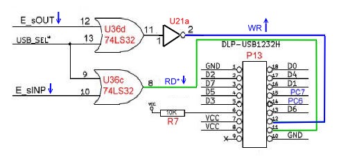
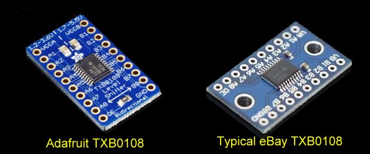
Finally the KiCAD schematic looks a little strange because I had to fool KiCAD into connecting the SMD TXB0108's to use the same pins as the adaptors. 
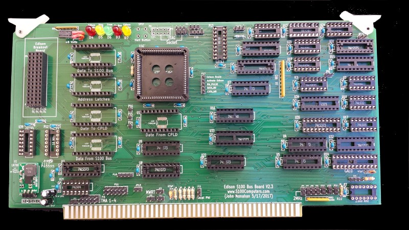
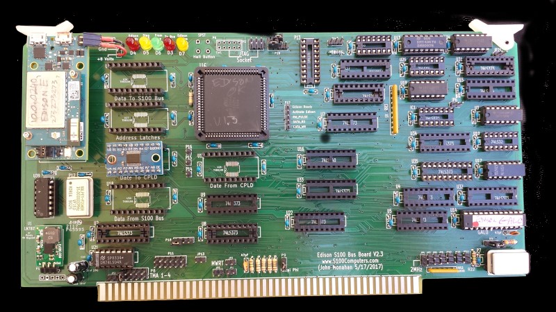
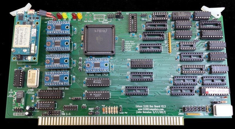
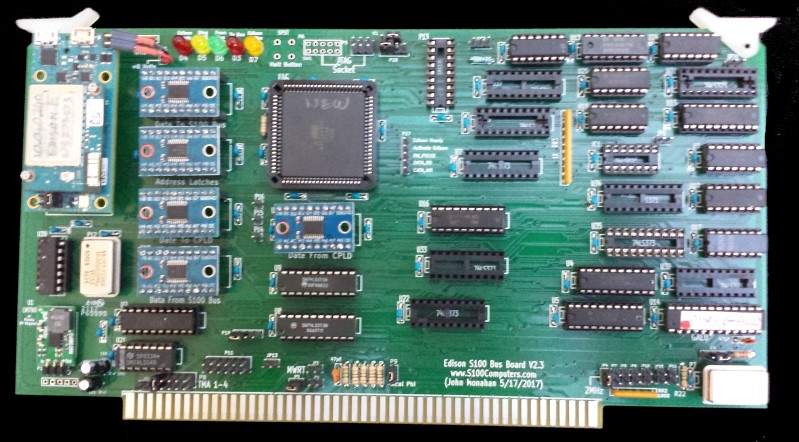
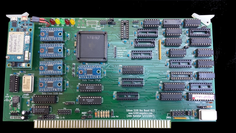
The most current version of this board is V2.3
 
Some time back Intel has scrapped the Edison and some of the links to their software on the website are all broken. The Edison boots up and you can get  WiFi running, but you cannot get the Eclipse IDE to instal as described here.

Kipp Yeakel added the following workaround:-
To get "Intel_Edison_Setup_Win_v2016.2.007" to install the drivers I used the attached workaround. This gets you to step 2, updating the firmware. This can be done manually using the 
iot-devkit-yp-poky-edison-20160606.zip image because it fits on the edison partition that comes up when you attach the USB connectors. However, if you want to  install iot-devkit-prof-dev-image-edison-20160606.zip the tool won't do this as you never get the next button enabled. I found that this is due to the RNDIS driver not installing. The problem is that the Intel certificate has expired. I had to restart my computer to install unsigned drivers to get this to work. See: https://www.maketecheasier.com/install-unsigned-drivers-windows10/ once your computer is booted, run the edison setup program again. Do the update firmware step pointing at your  already downloaded  iot-devkit-prof-dev-image-edison-20160606.zip file. The program will have 3 popups asking if you want to install unsigned drivers, I said yes to all. Then the image will be written to your edison module. I still have not gotten the next 2 steps in the setup program to work, but it doesn't matter as you can connect via PuTTY and  use the command "configure_edison --setup" to set the password and enable WiFi.  


 I was able to get the mraa library to work using the instructions I provided above. One thing I have not figured out yet is an easy way of setting up an IOT project. Here's what I did in windows, 

1) In the right most window of eclipse there is a "Create an IOT Project" selection. Click on it.

2) Pick Intel Edison from the next screen.

3) The next screen says Select target OS, but only Yocto shows up, press Next.

4) Pick Intel IoT C/C++ Project and Next

5) Choose your Target, it must be powered and all the way booted ~1minute.

6) Here is where it seems lacking... Put in a project name "S100_Edison" for example.

7) In the drop down box pick C -> Basic -> On-Board LED Blink

8) Click the Finish button. This will make a project folder with all the linkages.

9) Go to your workspace folder in windows explorer.

10) Navigate to the S100_Edison/src folder.

11) Copy John's S100_Edison.c file here.

12) Edit the "C.json" file, Change the line   "main": "blink.c", to   "main": "S100_Edison.c",

12) You should now be able to build the project.

13) During the build process it will prompt you for missing or miss-matched libraries between your build environment

and the actual Edison board. Allow it to update these.

14) You should now be able to debug or run the code.


Realizing that a number of people might want to utilize a board like this together with a group of people on the  Google Groups S100Computers Forum,  a "group purchases" is now open. If you would like a bare board please order there. Boards are $18 + shipping (PayPal) after you recieve your board.  Please do not e-mail me directly for boards.


A Production S-100 Board.
Realizing that a number of people might want to utilize a board like this together with a group of people on the  Google Groups S100Computers Forum, "group purchases" are made from time to time.  Please see here for more information.
   
 
The links below will contain the most recent schematic of this board.
Note, it may change over time and some IC part or pin numbers may not correlate exactly with the text in the article above.

Intel Edison Linux Install Package to run from Windows (64 Bit)     ( v2016.1.002    5/25/2016)
WinSCP download for Windows (64 Bit)                        (v5.8.3  5/26/2016)
Notepad++ download for Windows         
                          (v6.9.2   6/6/2016)
EdisonII Board KiCAD Schematic Pdf file                     V 2.3   (6/5/2017)
EdisonII CPLD Code (Zip file)                                   V2.3   (6/5/2017)

EdisonII CPLD Code (Pdf file)                                   V2.3   (6/5/2017)
Here is our (very often used) "GAL0" GAL code written in PALASM:-
GAL0.PDS (PALASM code).
Here is the same code written for WinCUPL (see here):-
GAL0.PLD (WinCUPL code).


S100_EdisonII C Code (Zip file)                                                V 1.3   (6/5/2017)
S100_EdisonII C Code (Pdf file)                              V1.3  (6/5/2017)
Edison V2.3 Board (.XLS) BOM                                         (7/5/2017  V2.3 board  Supplied by Rick Bromagem)
Edison V2.3 Board (.Pdf) BOM                                           (7/5/2017  V2.3 board  Supplied by Rick Bromagem)
EdisonII V2.4 Board KiCAD Folder
                               V2.4  (5/24/2018)
EdisonII V2.4 Gerber Files                                     V2.4  (5/24/2018)


Other pages describing my S-100 hardware and software.
Please click here to continue...

This page was last modified on 11/29/2021