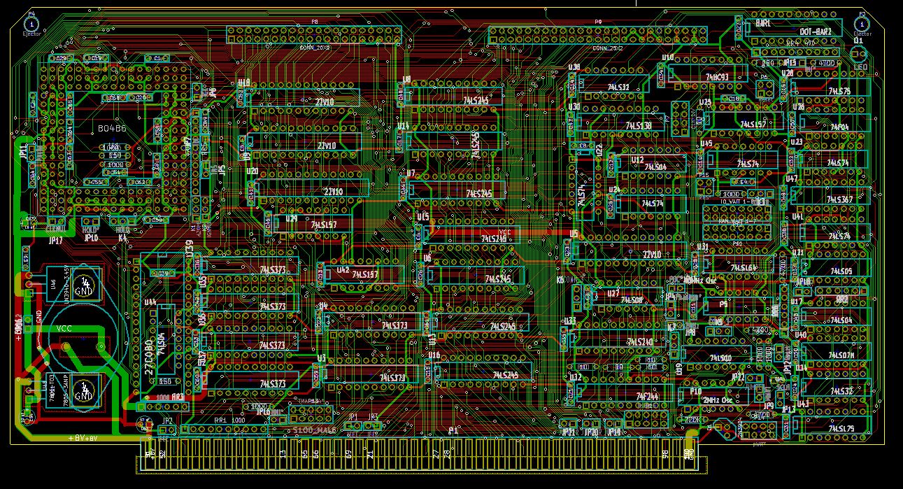
Thanks so much for that info Tom. I have just finished doing a layout of the 80486 on an S100 board. Took many tries with Freerouter to arrive at a solution. To my surprise the best arrangement was the CPU in the top LHS corner (not the middle of the board). Even with a Quad Pentium fully dedicated, it took 3 days to arrive at a solution! In the this current arrangement I have too board options. A 5V (5 Amp) 78H05 if an Intel 80486 chip is used, or, a 3 Amp 7805 TO-220 and an (up to) 3 Amp 4.45V LM3940 also in a TO-220 footprint. There is a jumper so the latter just supplies 3.45 volts to an AMD 5x68 CPU (along with its filter caps). I played a trick on freerouter so the bolt holes of the latter two regulators overlap with the 78H05. Since this is a prototype I will go with this first. Two questions on yours:- Should I use the 5V output to feed the 3.45 circuit or directly get it from the S100 8V line. Second, most important is the enough room on this board for all you have here. See the attached pictiure. Thanks John From: Tom Lafleur [mailto:laf...@lafleur.us] John Here are some notes on using the part... The trace between output pin to the diode and inductor should be very short, both parts need to be connected to the GND plane with short traces... (recommend using 2oz cooper) Input caps need to be low ESR type, I typ use 2 to 3 10-20uf ceramics, and one .1uf, again make them close to the part as you can... using 1210 parts sizes are easy to solder. even for us old guys.. Output caps again need to be low ESR type, one or two very near the inductor to GND. 100uf to 200 uf work great. I alway add room for the two trim resisters.. I always use 1% , if I'm using the fixed 5.0v part, the R from the FB pin is connect to the output V via a zero ohms R. My typical layout is as much GND plane as you can get under the LM22677 and the diode on both side of the board. Again 2 oz cooper is best. Lots of via in the gnd plane from top to bottom for better heat transfer and cut down on R losses. In most cases I put the LM22677 on the back side of the board, and some of the other parts on top.. I used multi-via on all traces to cut down on losses. I solder the thermal pad on the device via a ~ #4 plated hole. Ti has a program called webench that can be use to optimize part selection and design. I use it to trim my design. I run the device at 500Khz. WEBENCH can be run from the TI parts page... Here is the output from Webench for a 6 to 13v in, 5V out at 3.5amps, with a parts list.. (look like the diodes is missing from the TI schematic when they converted it to a PDF) ... If using >3.5 amp, the diode will need to be changed to one that >8amp, and then re run the webench for new plots. When your ready, I can help with the final part list... TI Data sheet: TI user guide:
|
Attachment:
S100 80486 V1.JPG
Description: JPEG image