Hi Don,
Yes, those are for support.
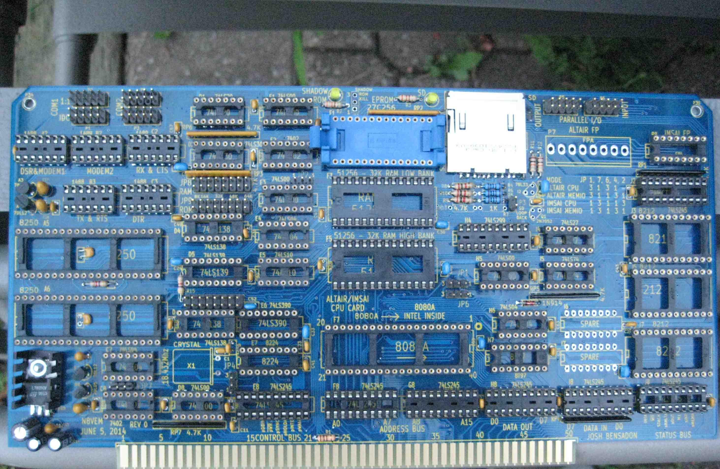
See Pics attached.
Fabio brought up a very good question about S-100 pin 53. The FP mini, IMSAI FP and ALTAIR FP use this pin for console, IEEE 696 grounds this pin. What are we to do?
Regards,
Josh
Date: Mon, 21 Jul 2014 16:50:26 -0700
Subject: Re: [N8VEM-S100:4659] Re: A/I 8080 CPU Builders Beware...
From: cap...@uxpro.com
To: n8vem...@googlegroups.com
--
-------------------------------
Don Caprio cap...@uxpro.com
http://www.uxpro.com
(925) 240-UNIX
--
You received this message because you are subscribed to the Google Groups "N8VEM-S100" group.
To unsubscribe from this group and stop receiving emails from it, send an email to n8vem-s100+...@googlegroups.com.
For more options, visit https://groups.google.com/d/optout.
Yes, those are for support.
See Pics attached.
Fabio brought up a very good question about S-100 pin 53. The FP mini, IMSAI FP and ALTAIR FP use this pin for console, IEEE 696 grounds this pin. What are we to do?
Regards,
Josh
Date: Mon, 21 Jul 2014 16:50:26 -0700
Subject: Re: [N8VEM-S100:4659] Re: A/I 8080 CPU Builders Beware...
From: cap...@uxpro.com
To: n8vem...@googlegroups.com
Josh,
Question on the SD card socket.
Are we suppose to solder the edges of the card socket (mid top right and left)
to the square pads on the PCB board? Not sure if this is a ground or just needed
to better secure the socket.
On Sun, Jul 13, 2014 at 6:04 PM, Crusty OMO <crus...@hotmail.com> wrote:
Hi Group,
Don, Fabio and myself have started to populate a board.
Here's where the errors come out of the shadows.
This is the feedback thus far...
1. C15 to C19 are the 3.3uF Tantalums, which are the capacitors that work on the voltage regulator outputs. I'm not sure how to calculate these, and they are most likely overrated. Other boards use 0.33uF successfully, I don't see why it won't work here either. Please feel free to use what you have, and/or comment.
2. The decoupler capacitor under IC-C2 was an error on my part when I was trying to squeeze parts to make room for traces, it can likely be omitted. There always tend to be a lot of decoupler capacitors around, I'm sure if you miss one it's not going to affect the operation.
3. There are 2 decoupling capacitors there with .2" lead spacing near RP3. I was needing a little more room to squeeze the traces through around those spots.
4. C1 is the 39pF next to the Crystal X1. I am using 33pF because that's in my junk box, I'm sure there's room for some tolerance here. Quite frankly, this capacitor should match the series loading of the crystal, and most crystals today don't need this any more, but I'm just cutting and pasting the circuit I've seen else where for the 8224.
5. You are going to find some capacitors also fit tight up against the IC's, that's ok, they like each other.
6. Remember to cut the trace to IC H4-Pin 11 and install a jumper as per the manual.
7. The 7805 does get hot, but it does not go above 50c on my prototype. If it does become an issue on your board, you can substitute some IC's for lower power IC's, eg. use the 16450 instead of 8250, 74HCT instead of 74LS (but keep the 74LS245's that drive the S-100 bus)
8. IC-H7 8T97 can be replaced with 74LS367
9. It's a little confusing in places what foot prints are decoupling capacitors and which are jumpers.
PS. There's definitely room for improvement, that's what Ver 2's are for! :)
Cheers,
Josh
--
You received this message because you are subscribed to the Google Groups "N8VEM-S100" group.
To unsubscribe from this group and stop receiving emails from it, send an email to n8vem-s100+...@googlegroups.com.
For more options, visit https://groups.google.com/d/optout.
--
-------------------------------
Don Caprio cap...@uxpro.com
http://www.uxpro.com
(925) 240-UNIX
--
You received this message because you are subscribed to the Google Groups "N8VEM-S100" group.
To unsubscribe from this group and stop receiving emails from it, send an email to n8vem-s100+...@googlegroups.com.
For more options, visit https://groups.google.com/d/optout.
