Hey team,
I'm intrigued by Josh's suggestion to add a heartbeat LED for the clock signal.
Just not sure how it's implemented since I'm still a newbie at TTL design. Considered
asking this question off list as to not look like such a dummy, but I think it would be
of interest to others. Wise council from the elders is appreciated.
The clock signal pulses. Does it have enough current to drive an LED? If
so what sort of disadvantages? Will it degrade the signal? I think the answer
is to drive the led from a driver like maybe a 74LS244 ? (74LS125, 74LS367 ?)
Regarding adding +5v to the board for a logic probe. I think a TO-220 LM7805
is overkill. Sounds like a job for the L78L05 TO-92. It's limited to 100ma
output. Is that enough to drive one IC (24ma) and a logic probe plus one or two LED's?
I know that Zener diodes can also be used as a voltage regulator but would require
a few more components like a capacitor and resistor.
Thank you.
On 01/29/15 07:12 AM, Crusty OMO wrote:
Hi Don,--
This is an excellent idea. Of course, there are more features that some might wish for...
On one hand, a board for break out purpose only serves the purpose.
On the other hand, perhaps consider these features....
-add pins to mount a female S-100 connector (thus making it like a mini-extender & break out)
-add power LED's
-add voltage check LED's (only lights if the power is within a fixed tolerance)
-add supply ripple LED's, lights if there is excessive ripple on the power supply
-add LED's to various signal lines, data and address bus.
Of course, each of those features would add complexity that requires board space and increases the price... I would rank the S-100 female and data/address LED's as minor features that add much complexity. But the power, voltage & ripple LED's shouldn't be too difficult. An LED on a divider to indicate clock would be easy too. Always nice to see a flashing LED as a sign of the heart beat.
Food for thought... but if you do go with the basic break out board, count me in for 2 :)
Regards,
Josh
Date: Wed, 28 Jan 2015 23:47:36 -0800
From: ilv...@gmail.com
To: n8vem...@googlegroups.com
Subject: [N8VEM-S100:6101] RFC - S100 Bus Test Point PCB
When I'm doing testing on S-100 boards in my bus extender card
I find it difficult to find pins especially on the back of the board.
Tried various methods mostly using labels and hand writing bus
pin definitions on the limited space. Have you ever wished there
was a better way? Me too.
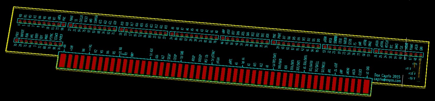
Maybe there is a better way. Perhaps there's a better mouse trap
but I came up with this simple PCB design that you can mount in
a bus extender card to make life a little easier.
Curious if any of you would find this useful. Might be a bit of an overkill
since were really only interested in a handful of bus signals, but I tried
to cover all the bases. Some of the more sophisticated boards are making
use of more signals and expanded bus addressing.
I'll be ordering a limited quantity for myself and would be happy to
include others. The board would be about $3.50 with qty 25 pricing,
$2.00 qty 50 (2 for price of 1).
Thanks for your feedback.
--
Don Caprio
ilv...@gmail.com
--
You received this message because you are subscribed to the Google Groups "N8VEM-S100" group.
To unsubscribe from this group and stop receiving emails from it, send an email to n8vem-s100+...@googlegroups.com.
For more options, visit https://groups.google.com/d/optout.
You received this message because you are subscribed to the Google Groups "N8VEM-S100" group.
To unsubscribe from this group and stop receiving emails from it, send an email to n8vem-s100+...@googlegroups.com.
For more options, visit https://groups.google.com/d/optout.
--
Don Caprio
ilv...@gmail.com